
Dielectric resonator, filter, duplexer, oscillator and communication apparatus

a technology of dielectric resonators and oscillators, applied in the direction of resonators, electrical devices, coupling devices, etc., can solve the problems of difficult or impossible formation using a uniaxial press, increased manufacturing costs, and inability to stabilize formation

Inactive Publication Date: 2002-08-06
MURATA MFG CO LTD
View PDF11 Cites 7 Cited by
  • Summary
  • Abstract
  • Description
  • Claims
  • Application Information

AI Technical Summary

Benefits of technology

According to the above structure and arrangement, the mounting face of the supporting base section is ring-shaped, and the width thereof (in other words, the thickness of the dielectric constituting the supporting base section) is reduced. Therefore, the effective dielectric constant of the supporting base section is significantly reduced. This minimizes reduction in the unloaded Q value of the resonator.
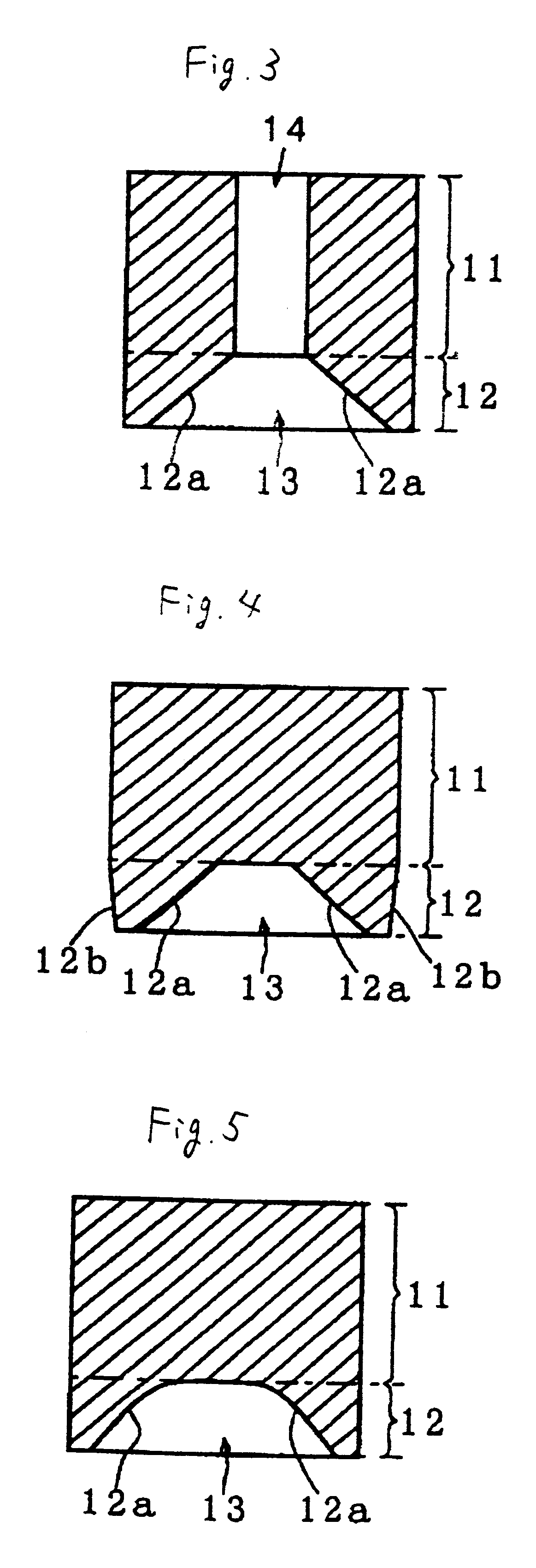
Further, the dielectric resonator has a simple shape, since only the above-mentioned concave trapezoidal cross section is formed in the supporting base section, and no right-angled step section is formed. Therefore, sharp variations in the formation density of the formed body are substantially avoided. Therefore, the dielectric resonator does not become deformed and reduced in mechanical strength and can be easily formed by the use of a low-cost forming method using a uniaxial-pressuring press. Starting with the reduced width of the ring shape at the mounting face of the supporting base section, the thickness of the dielectric constituting the supporting base section becomes greater in the direction toward the resonator section. This prevents reduction in the mechanical strength of the formed body.
Further, a filter, a duplexer, and an oscillator may be provided with the above described dielectric resonator. Thereby, manufacturing costs can be reduced, and good characteristics thereof can be obtained.
Further, a communication apparatus may be provided with one of the above described filter, duplexer, and oscillator. Thereby, a communication apparatus with a good characteristics can be obtained cheaply.

Problems solved by technology

In this case, however, a problem is that adhering work for the supporting base section is required, and manufacturing costs are increased thereby.
Also, since the shape of the supporting base section is complicated, problems are raised in that stable formation is impossible, and formation using a uniaxial pressuring press is difficult or impossible.
Other problems are raised by the complicated shape of the forming die.
Therefore, manufacturing costs therefor are high, and the service life thereof is short.
Also, in the above-described dielectric resonator, since the outside diameter of the supporting base section is smaller than that of the resonator section, problems are raised in that the dielectric resonator cannot be stably mounted in a cavity by automatic mounting.
This trapped air can cause positional deviations after adhesion.

Method used


Image

  • Dielectric resonator, filter, duplexer, oscillator and communication apparatus
  • Dielectric resonator, filter, duplexer, oscillator and communication apparatus
  • Dielectric resonator, filter, duplexer, oscillator and communication apparatus

Examples


first embodiment

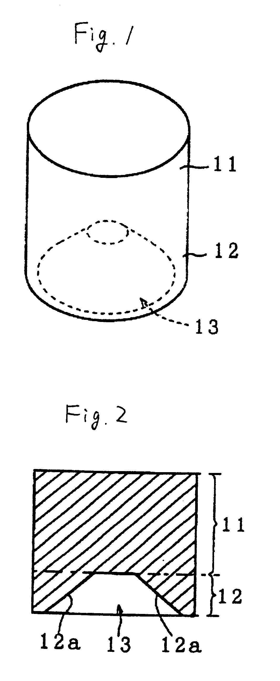
Referring to FIGS. 1 and 2, a description will be given of the arrangement of a dielectric resonator according to the present invention. FIG. 1 is a perspective view of a dielectric resonator, and FIG. 2 is a cross-sectional view thereof.

The dielectric resonator of this embodiment is configured of a substantially cylindrical dielectric body, in which a resonator section 11 and a supporting base section 12 are formed as a single unit. The supporting base section 12 is formed to have the same outside diameter as that of the resonator section 11. A concave section 13 with a trapezoidal cross sectional shape is formed in the supporting base section 12. That is, the inside diameter decreases so that the concave section 13 is tapered in the direction from the end face, used as a mounting face, toward the resonator section 11, and the outer peripheral portion of the end face is ring-shaped.

Specifically, the concave section 13 is coaxial with respect to the central axis of the dielectric re...

fifth embodiment

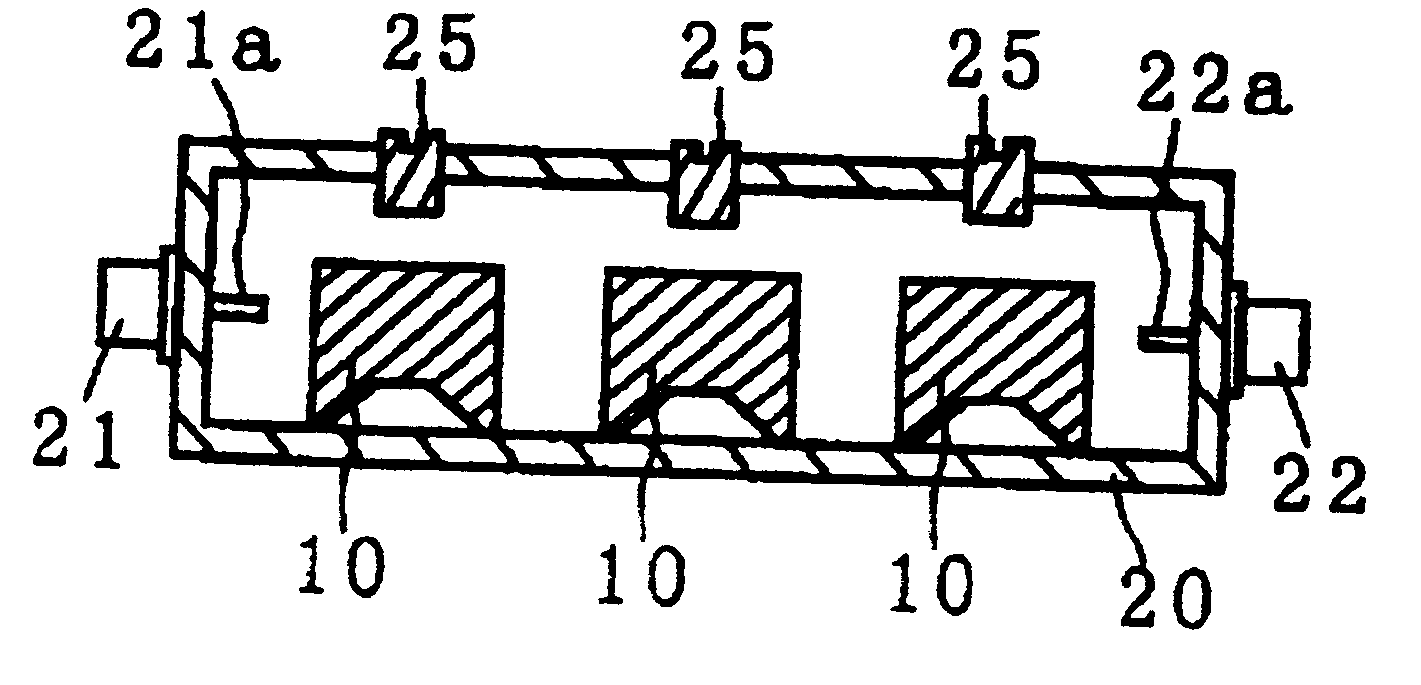
Hereinbelow, referring to FIG. 6, a description will be given of a filter according to the present invention. The filter of this embodiment is configured such that three dielectric resonators 10 are provided in a cavity 20 that has coaxial connectors 21 and 22 installed at both ends as input / output connectors. In the coaxial connectors 21 and 22, probes 21a and 22a are provided so as to electromagnetically couple with the corresponding dielectric resonators 10. Each of the dielectric resonators 10 is immobilized such that the mounting face of the supporting base section 12 is adhered with an adhesive or the like onto the bottom wall of the cavity 20. Also, screws 25 for adjusting frequency are provided above the dielectric resonators 10. The cavity 20 is a conductive housing that has either a metal surface, or a ceramic surface on which conductors are formed. The number of dielectric resonators is not restricted to three. One, two, or more than three dielectric resonators may be use...

sixth embodiment

Hereinbelow, referring to FIG. 7, a description will be given of a duplexer according to the present invention. The duplexer of this embodiment has a cavity 20 for containing two dielectric resonators 10 that compose a transmitting filter 31, and three dielectric resonators that compose a receiving filter 32. As an input / output connector for the transmitting filter, a coaxial connector 21 is provided on one end of the cavity 20. As an input / output connector for the receiving filter, a coaxial connector 22 is provided on the other end thereof. Also, as an antenna input / output connector commonly coupled with both the transmitting and receiving filters, a coaxial connector 23 is provided on a central portion of the sidewall of the cavity 20. The coaxial connectors 21, 22, and 23 have probes 21a, 22a, and 23a, respectively, provided for electromagnetically coupling with the corresponding dielectric resonators 10. Each of the individual dielectric resonators 10 is immobilized such that t...


PUM


Abstract

A dielectric resonator comprising a resonator section and a supporting base section which are made of the same dielectric material as a single unit. The resonator section and the supporting base section have substantially the same outside diameter. A concave section having a trapezoidal cross-sectional shape is provided within the supporting base section such that the inside diameter of the supporting base section becomes smaller in the direction from the end face, which is used as a mounting face, and toward the resonator section.

Description

1. Field of the InventionThe present invention relates to a TE01.delta.-mode dielectric resonator having a resonator section and a supporting base section which are made of the same dielectric material as a single unit; a filter, a duplexer, and an oscillator each using the dielectric resonator; and a communication apparatus using the above.2. Description of the Related ArtGenerally, dielectric resonators of the aforementioned type have a structure in which a supporting base having a low dielectric constant is adhered to a resonator section having a high dielectric constant. In this case, however, a problem is that adhering work for the supporting base section is required, and manufacturing costs are increased thereby.In this situation, there is proposed a dielectric resonator having a resonator section and a supporting base section that are formed of the same dielectric material as a single unit (Japanese Unexamined Patent Application Publication No. 8-222917). In the dielectric re...

Claims


Application Information

Patent Timeline
IPC IPC(8): H01P7/10H01P1/20H01P1/213
CPCH01P7/10H01P1/20H01P1/2138H01P7/06
Inventor KURISU, TORUABE, HIROTSUGUHIGUCHI, YUKIO
Owner MURATA MFG CO LTD
Learn More