Helical antenna, antenna unit, composite antenna

a technology of composite antennas and antenna leads, applied in the direction of helical antennas, non-resonant long antennas, radiating elements structural forms, etc., can solve the problems of requiring a large amount of material on manufacturing, remarkably difficult to really wind the plurality of antenna lead members around the outer peripheral surface, and a large amount of solid cylindrical components. to achieve the effect of strengthening the structur

Inactive Publication Date: 2002-08-06
MITSUMI ELECTRIC CO LTD
View PDF8 Cites 29 Cited by
  • Summary
  • Abstract
  • Description
  • Claims
  • Application Information

AI Technical Summary

Benefits of technology

It is therefore an object of the present invention to provide a helical antenna which is capable of strengthening in structure without weighting.
According to an eleventh aspect of this invention, a method is of adjusting a resonance frequency of a helical antenna according to the tenth aspect of this invention so as to match a desired resonance frequency. The method comprises the steps of preparing the cylindrical dielectric core having a length so that the helical antenna enables to receive a frequency lower than the desired resonance frequency, and of stripping the belts of the flexible insulator film in the order of being apart from a tip end of the cylindrical dielectric core to decrease a length of the conductive pattern, thereby matching the resonance frequency of the helical antenna with the desired resonance frequency.

Problems solved by technology

On the other hand, it is remarkably difficult to really wind the plurality of antenna lead members around the outer peripheral surface of the cylindrical member or the bobbin in the helix fashion.
This is because the solid cylindrical member has a heavy weight and requires a large amount of material on manufacturing.
However, the cutting method is disadvantageous in that it takes a lot of time in the manner which will later be described in detail.
In addition, when the helical antenna is mounted on the automobile, vibrations and shocks are given to the helical antenna.
Under the circumstances, sufficient antivibration and anti-shockness are not obtained in the above-mentioned conventional helical antenna in which the antenna pattern film is fixed on the outer peripheral surface of the bobbin by means of the adhesive tape, the adhesive agent, or the like.
Inasmuch as the bottom case is required in the conventional antenna unit, the bottom case hinders miniaturization of the antenna unit and restricts design of the antenna unit.
With this structure, assembling of the antenna unit is complicated and it is difficult to precisely evaluate performances at an output of the phase shifter and an input of the low-noise amplifier after assembling of the antenna unit.
Inasmuch as the ground plate has the plane shape, the conventional antenna unit is disadvantageous in that it is difficult to decrease ground noises and to improve an antenna sensitivity.
As a result, the conventional composite antenna is disadvantageous in that a lot of parts are required and a manufacturing cost is expensive.

Method used


Image

  • Helical antenna, antenna unit, composite antenna
  • Helical antenna, antenna unit, composite antenna
  • Helical antenna, antenna unit, composite antenna

Examples


first embodiment

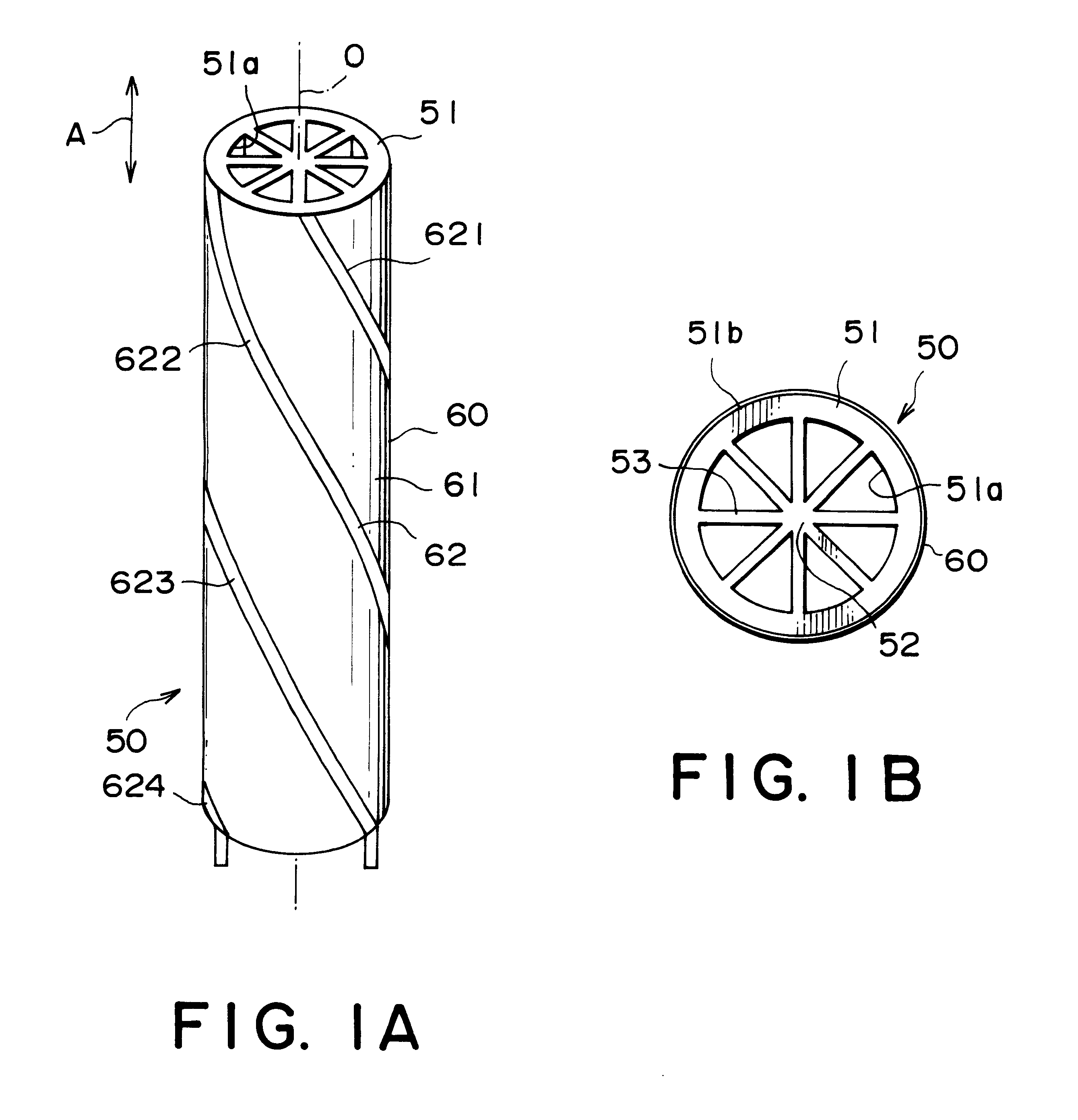
Referring to FIGS. 1A and 1B, the description will proceed to a helical antenna 50 according to this invention. FIG. 1A is a perspective view of the helical antenna 50. FIG. 1B is a plan view of the helical antenna 50.

The illustrated helical antenna 50 comprises a hollow cylindrical member 51 made of insulator. The hollow cylindrical member 51 may be called a bobbin or a cylindrical dielectric core. The hollow cylindrical member 51 has a center axis O extending in a longitudinal direction A.

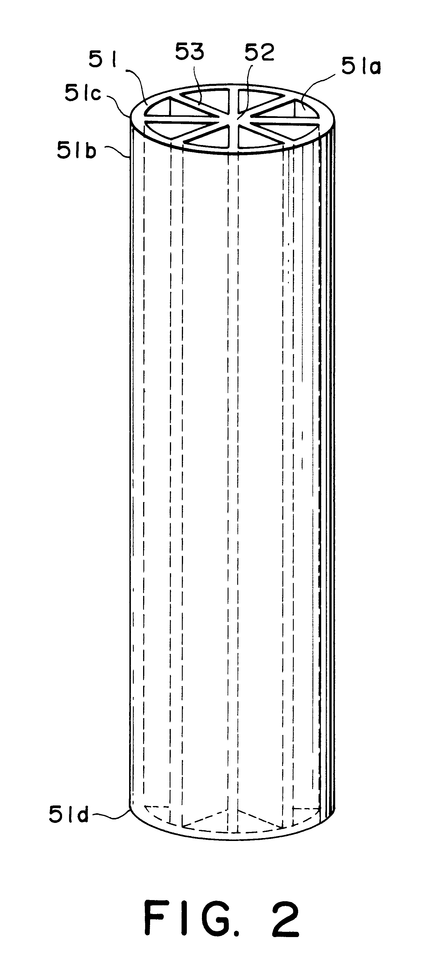
As shown in FIG. 2, the hollow cylindrical member 51 has an inner peripheral surface or wall 51 a and an outer peripheral surface or wall 51b. The helical antenna 50 comprises a center rod 52 which is coaxial with the center axis O. The helical antenna 50 further comprises eight ribs 53 which are disposed between the center rod 52 and the inner peripheral surface 51a of the hollow cylindrical member 51. The eight ribs 53 symmetrically extend in a radial manner at equal angular intervals as shown ...

second embodiment

Referring to FIG. 6, the description will proceed to a helical antenna 50A according to this invention. The illustrated helical antenna 50A comprises the hollow cylindrical member 51 made of insulator. The hollow cylindrical member 51 has a relative dielectric constant or a relative permittivity .di-elect cons. r of a range between two and four. The hollow cylindrical member 51 has the center axis O which extends in the longitudinal direction A, the inner peripheral wall 51a, and the outer peripheral wall 51b. The hollow cylindrical member 51 has the upper end portion 51c. The hollow cylindrical member 51 is made of material such as plastic.

The helical antenna 50A further comprises the first through the fourth leads 621 to 624 which are wound around the outer peripheral wall 51b of the hollow cylindrical member 51 in the helix fashion as shown in FIG. 6. In the example being illustrated in FIG. 6, inasmuch as the first through the fourth leads 621 to 624 are wound around the outer p...

third embodiment

Referring to FIG. 11, the description will proceed to a helical antenna 50B according this invention. The illustrated antenna 50B comprises a hollow cylindrical dielectric core 51 made of insulator (dielectric). The hollow cylindrical dielectric core 51 has the center axis O extending in the longitudinal direction A and the outer peripheral surface 51b. In the example being illustrated, the hollow cylindrical dielectric core 51 is made of substantially plastic having a hollow cylindrical shape.

The helical antenna 50B further comprises the first through the fourth antenna lead members 621, 622, 623, and 624 each of which is made of conductor. The first through the fourth antenna lead members 621 to 624 are wound around the outer peripheral surface 51b of the hollow cylindrical dielectric core 51 except for a tip portion 50f of the hollow cylindrical dielectric core 51. The first through the fourth antenna lead members 621 to 623 substantially have the same size, the same shape, and t...


PUM


Abstract

In a helical antenna comprising a hollow cylindrical member having an inner peripheral surface and an outer peripheral surface and an antenna pattern film wound around the outer peripheral surface of the hollow cylindrical member, the helical antenna further comprises a center rod coaxial with a center axis of the hollow cylindrical member and at least three ribs disposed between the center rod and the inner peripheral surface of the hollow cylindrical member. The ribs symmetrically extends in a radial manner at equal angular intervals. The hollow cylindrical member, the center rod, and the ribs preferably may be integrally molded out of plastic. The antenna pattern film may comprise a flexible insulator film and a conductive pattern formed on the flexible insulator film. The conductive pattern has at least one antenna lead member which is wound around the outer peripheral surface of the hollow cylindrical member in a helix fashion.

Description

BACKGROUND OF THE INVENTION:This invention relates to a digital radio receiver for receiving an electric wave from an artificial satellite (which may be called a "satellite wave") or an electric wave on the ground (which may be called a "ground wave") to listen in a digital radio broadcasting and, in particular, to an antenna for use in the digital radio receiver.In recent years, a digital radio receiver, which receives the satellite wave or the ground wave to listen in the digital radio broadcasting, has been developed and is put to practical use in the United States of America. The digital radio receiver is mounted on a mobile station such as an automobile and can receive an electric wave having a frequency of about 2.3 gigahelts (GHz) to listen in a radio broadcasting. That is, the digital radio receiver is a radio receiver which can listen in a mobile broadcasting. In addition, the ground wave is an electric wave in which a signal where the satellite wave is received in an earth...

Claims


Application Information

Patent Timeline
Patent Type & Authority Patents(United States)
IPC IPC(8): H01Q1/36H01Q11/08H01Q11/00H01Q1/38
CPCH01Q1/362H01Q1/38H01Q11/08
Inventor NORO, JUNICHIAWA, HIROKAZUMIYATA, MASAAKI
Owner MITSUMI ELECTRIC CO LTD
Why Eureka
Try Eureka