Pluggable transceiver module having rotatable release and removal lever with living hinge

Inactive Publication Date: 2002-08-06
STRATOS INT
View PDF10 Cites 264 Cited by
  • Summary
  • Abstract
  • Description
  • Claims
  • Application Information

AI Technical Summary

Benefits of technology

A further object of the present invention is to provide a release and removal mechanism that can be easily assembled.
An additional object of the present inv

Problems solved by technology

The requirement of a tool for removing the transceiver module is not only inconvenient, but also prevents an operator from removing a transceiver m

Method used


Image

  • Pluggable transceiver module having rotatable release and removal lever with living hinge
  • Pluggable transceiver module having rotatable release and removal lever with living hinge
  • Pluggable transceiver module having rotatable release and removal lever with living hinge

Examples


Embodiment Construction

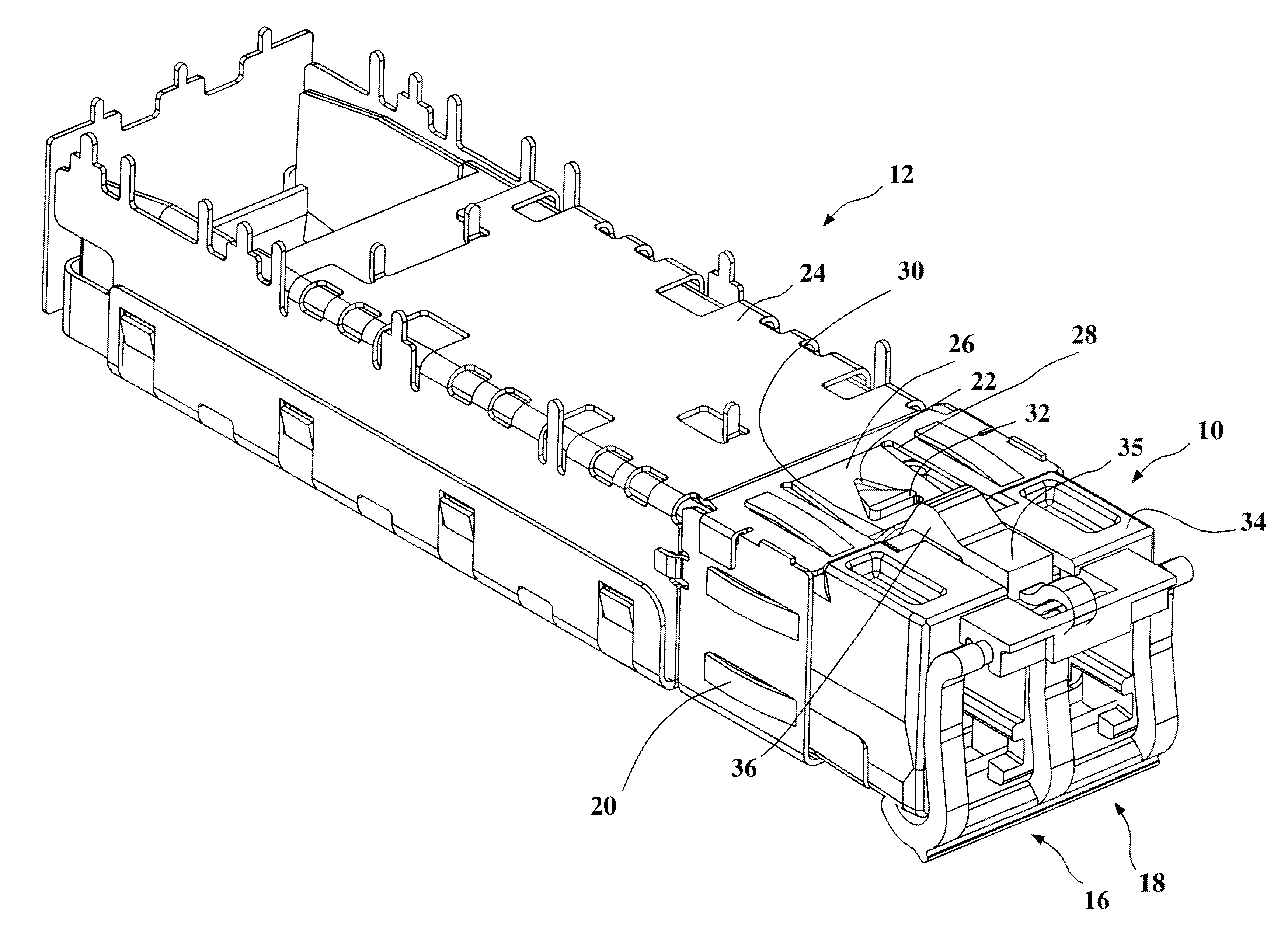
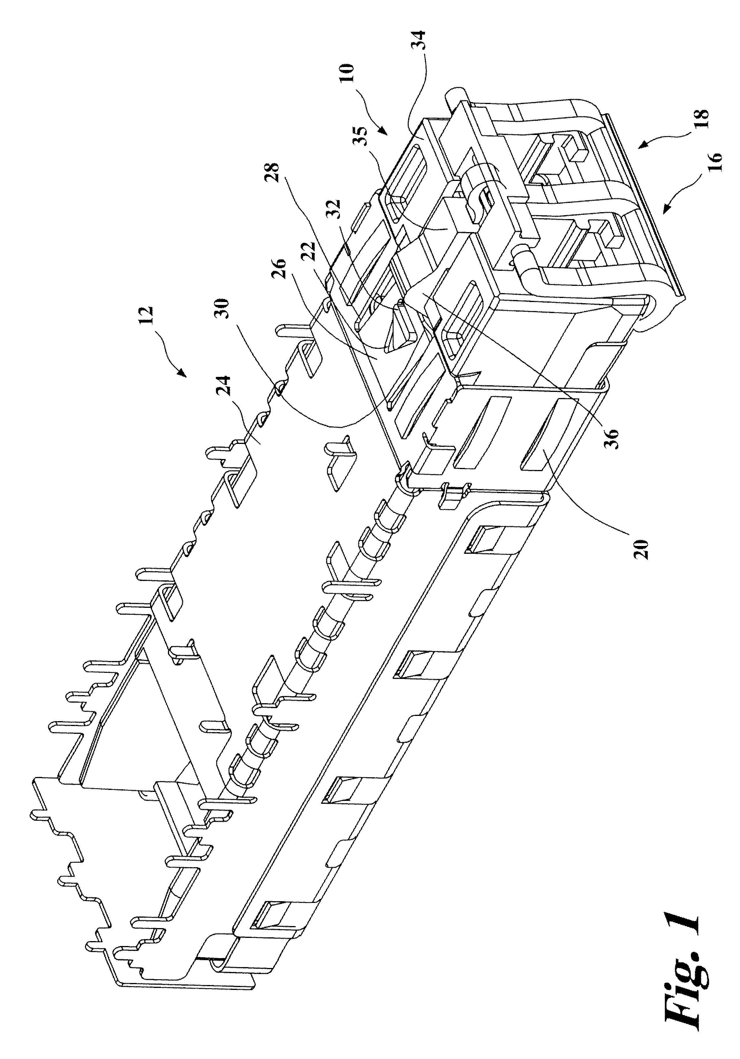
Referring now to the drawings, FIG. 1 shows a pluggable transceiver module 10 within a socket or receptacle 12. The receptacle 12 is generally to be mounted to a printed circuit board (not shown). The pluggable transceiver module 10 is shown inserted within the receptacle 12. The pluggable transceiver module 10 includes an optical input 16 and an optical output 18. In some configurations, both ports 16,18 can be receivers or transmitters. Contacts 20 are cut and formed out of the receptacle 12. The contacts 20 are designed to contact and ground the receptacle 12 to a stacked array (not shown). The receptacle 12 is preferably constructed out of a conductive metal.

The receptacle 12 includes a slot 22 on a base 24 of the receptacle 12. The slot 22 is formed in a bendable portion 26 of the base 24. The bendable portion 26 is formed by cutting slits 28 (FIG. 4) into the base 24 of the receptacle 12. The bendable portion 26 includes a lip 30. During insertion of the transceiver module 10 ...


PUM


Abstract

A pluggable transceiver module having a housing with a first side and a face perpendicular to the first side, and a tab extending beyond the surface of the first side, and the tab sized to mate with a slot in a receptacle of a host device for receiving the pluggable transceiver module housing, an elongated member slidably mounted to the first side of the housing and having an internal end and an external end, a wedge on the internal end of the elongated member, wherein sliding the elongated member inward causes the wedge to slide between the tab and the slot on the receptacle and remove the tab from within the slot, thereby releasing the pluggable transceiver module from the receptacle, and a lever rotatably mounted via an axle proximate the face of the pluggable transceiver module, said axle being connected to the external end of the elongated member such that rotating the lever away from the face of the pluggable transceiver cause the rotating axle to push the elongated member inward and drive the wedge between the tab and the slot in order to release the pluggable transceiver module from the receptacle.

Description

The present invention relates generally to pluggable transceiver modules, and more particularly, to a pluggable transceiver module having a rotatable release and removal lever utilizing a living hinge.Optoelectronic transceivers are utilized to interconnect circuit cards of communication links and other electronic modules or assemblies. Various international and industry standards define the type of connectors used to interface computers to external communication devices such as modems, network interfaces, and other transceivers. A well-known type of transceiver module developed by an industry consortium and known as a Gigabit Interface Converter (GBIC) provides an interface between a computer and an Ethernet, Fibre Channel, or other data communication environment. U.S. patents identified under issued U.S. Pat. Nos. 5,879,173, 5,864,468, 5,734,558, 5,717,533, and U.S. Pat. No. Re 36,820, originally assigned to Methode Electronics, Inc, and now assigned to Stratos Lightwave, both in ...

Claims


Application Information

Patent Timeline
IPC IPC(8): G11B33/12H01R13/633G02B6/42H01R13/658
CPCH01R13/6335G02B6/4246G02B6/4292H01R13/65802H01R13/6582
Inventor PETERSON, BRUCE A.MEDINA, RAULPETERSON, FRANK J.
Owner STRATOS INT
Why Eureka
Try Eureka