Single rotor turbine engine

a single-rotor, turbine engine technology, applied in the direction of machines/engines, efficient propulsion technologies, liquid fuel engines, etc., can solve the problems of shaft whipping, vibration, overheating bearings, and difficult to keep blades balanced in large-scale turbine engines

Inactive Publication Date: 2002-08-13
LOS ALAMOS NATIONAL SECURITY
View PDF35 Cites 136 Cited by
  • Summary
  • Abstract
  • Description
  • Claims
  • Application Information

AI Technical Summary

Benefits of technology

To achieve the foregoing and other objects, and in accordance with the purposes of the present invention, as embodied and broadly described herein, there has been invented a turbine engine with a single rotor (rotating disk impeller) which cools the engine, functions as a radial compressor, pushes air through the engine to the ignition point, and ac...

Problems solved by technology

Long shafts necessary to accommodate two separate rotor blades in large state-of-the-art turbine engines are difficult to keep balanced and wear out.
Shaft whip, vibration, and overheated bearings are common problems.
In these turbine engines, damage to rotor blades by hot exhaust temperatures is common.
However, the firing temper...

Method used


Image

  • Single rotor turbine engine
  • Single rotor turbine engine
  • Single rotor turbine engine

Examples


second embodiment

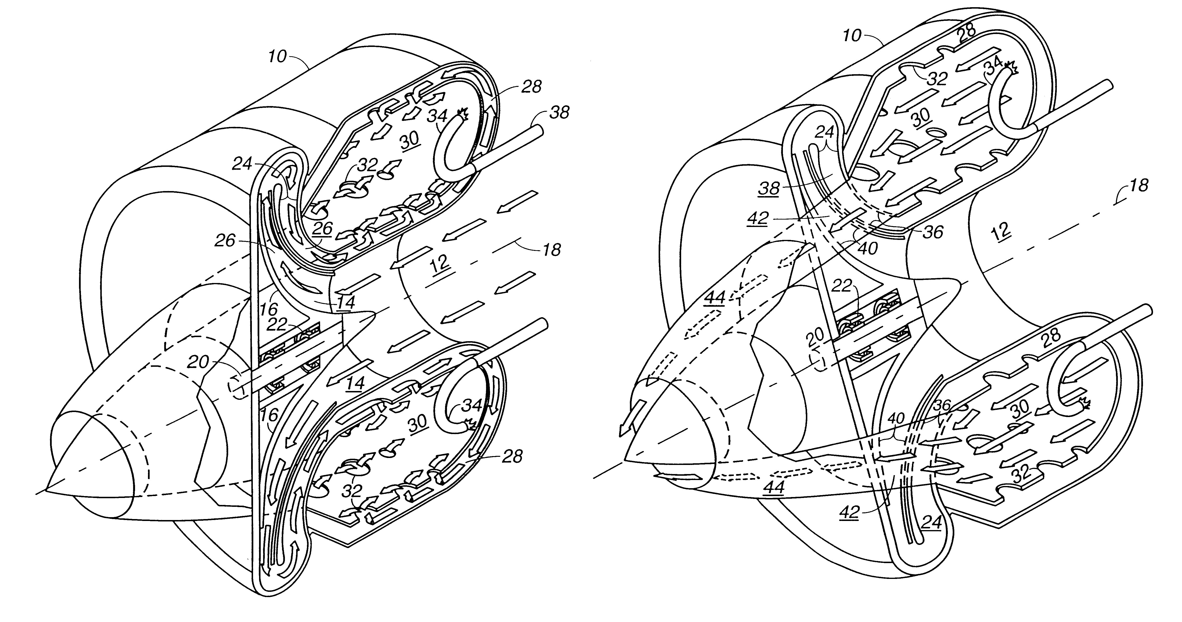
As described with respect to the second embodiment herein, power can also be extracted by incorporating an electrical generator in the device. It is presently preferred to use radial turbine passages for the exhaust air flow in this alternative configuration of the invention since more power can be extracted using a radial turbine.

Using a single rotor to combine the rotating parts of the turbine engine eliminates the need for a long shaft and the dynamic problems associated therewith. In the invention turbine engines, only a single rotating part needs to be balanced. The bearings are located where intake air will keep them cool.
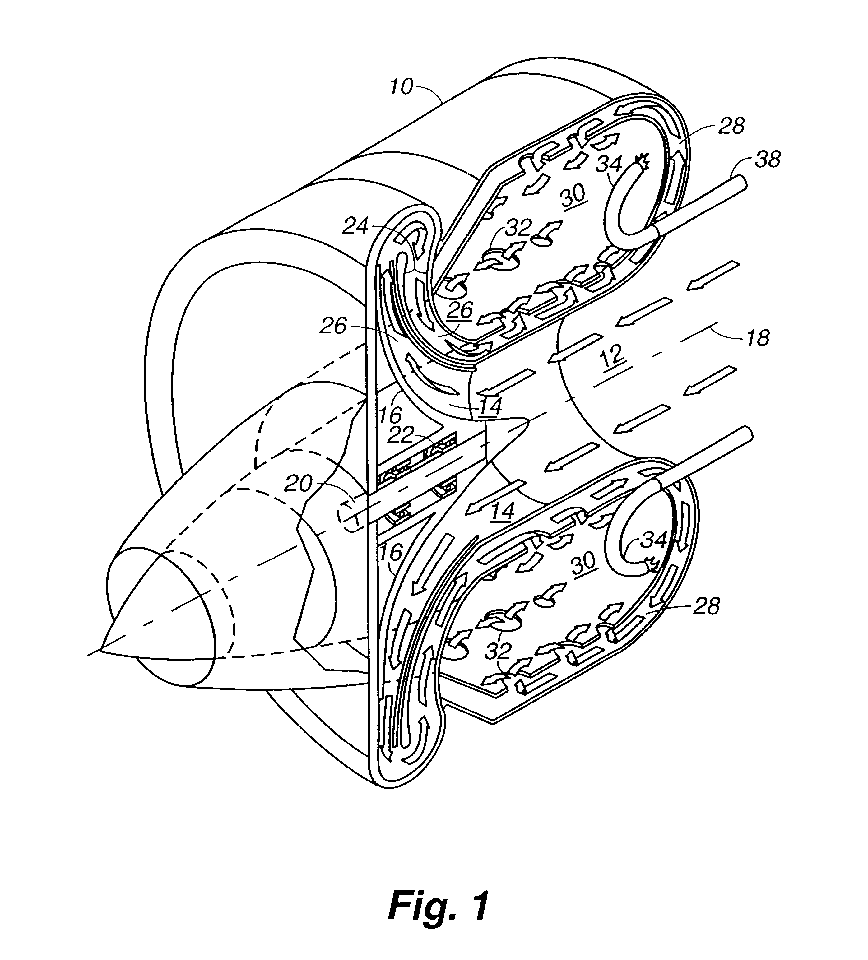
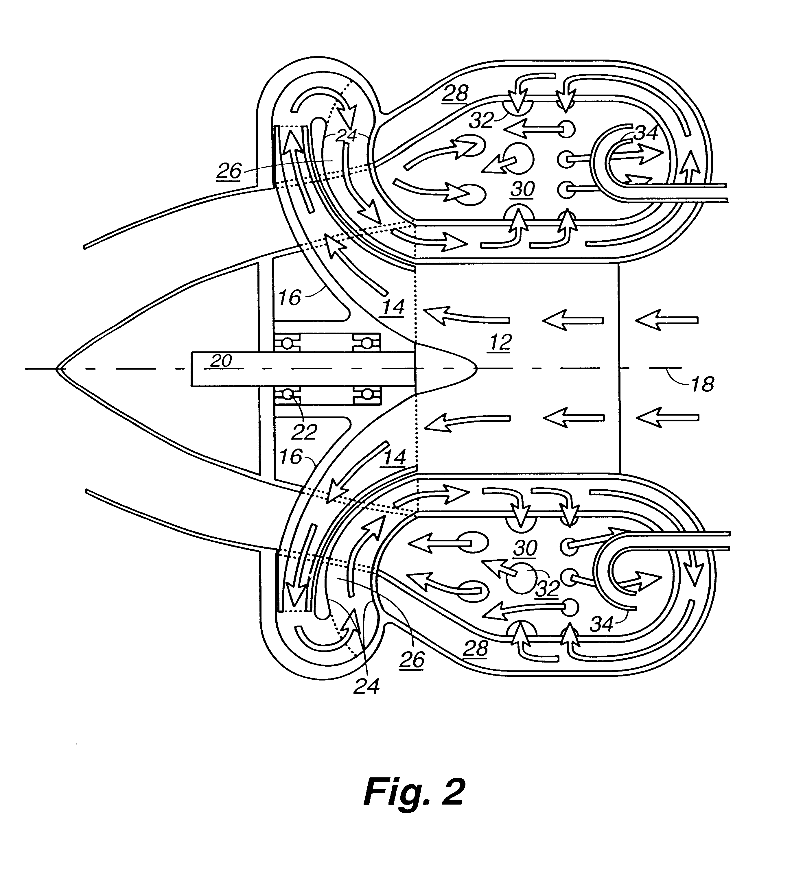
first embodiment

With reference to the drawings, FIG. 1 shows an orthogonal cross section taken through the intake passages of the invention turbine engine. As depicted in FIG. 1, within an engine housing 10 a passage for intake air 12 is fluidly connected to radially disposed passages (radial compressor passages 14) in a rotor 16. The rotor 16 is positioned to rotate about an axis of rotational symmetry 18 on a stationary shaft 20. The rotor 16 is supported by bearings 22. The intake air is compressed using the radial compressor passages 14 in the rotor 16 in the same manner as air is compressed in a conventional centrifugal compressor.

Still with reference to FIG. 1, a stationary diffuser 24 converts the velocity of the air coming from the radial compressor passages 14 in the rotor 16 to a radially inward diffuser flow path 26, thereby producing a slower, higher pressure air flow. The pressurized air is conducted into a space 28 between the housing 10 and a conventional gas turbine type combustion ...


PUM


Abstract

There has been invented a turbine engine with a single rotor which cools the engine, functions as a radial compressor, pushes air through the engine to the ignition point, and acts as an axial turbine for powering the compressor. The invention engine is designed to use a simple scheme of conventional passage shapes to provide both a radial and axial flow pattern through the single rotor, thereby allowing the radial intake air flow to cool the turbine blades and turbine exhaust gases in an axial flow to be used for energy transfer. In an alternative embodiment, an electric generator is incorporated in the engine to specifically adapt the invention for power generation. Magnets are embedded in the exhaust face of the single rotor proximate to a ring of stationary magnetic cores with windings to provide for the generation of electricity. In this alternative embodiment, the turbine is a radial inflow turbine rather than an axial turbine as used in the first embodiment. Radial inflow passages of conventional design are interleaved with radial compressor passages to allow the intake air to cool the turbine blades.

Description

This invention relates to gas turbine engines and more particularly to gas turbine engines which have only a single rotor that serves both as a radial compressor and as an axial turbine.Simple turbine engines generally have two rotors or sets of rotors, one for compressing the intake air and the other for using some of the exhaust energy to power the compressor.Large turbines with over 500 kW output power such as those in commercial aircraft and electric power generating stations use both a multistage axial compressor and an axial turbine. Long shafts necessary to accommodate two separate rotor blades in large state-of-the-art turbine engines are difficult to keep balanced and wear out. Shaft whip, vibration, and overheated bearings are common problems.Either axial or radial turbines are employed in small turbine engines used for local power generators for backup and peak shedding. In these turbine engines, damage to rotor blades by hot exhaust temperatures is common.The higher the ...

Claims


Application Information

Patent Timeline
IPC IPC(8): F01D25/08F01D25/12F01D5/02F02C3/00F01D5/04F02C3/045F02C3/073F04D25/02F04D25/04F04D29/28
CPCF01D5/022F01D5/046F01D5/048F01D25/12F02C3/045F02C3/073F04D25/045F04D29/284F05D2250/82Y02T50/673Y02T50/675Y02T50/60
Inventor PLATTS, DAVID A.
Owner LOS ALAMOS NATIONAL SECURITY
Why Eureka
Try Eureka