Connection device for osteosynthesis

a technology of connecting device and osteosynthesis, which is applied in the field of connecting device for osteosynthesis, can solve the problems of increasing the amount of handling that the surgeon needs to perform, increasing the length of time required to install the device, and increasing the size of the connection device, so as to reduce the size of the locking piece, the risk of disconnection or changing their respective positions

Inactive Publication Date: 2002-08-13
SOCIETE DE GENIE MEDICAL SGM
View PDF15 Cites 54 Cited by
  • Summary
  • Abstract
  • Description
  • Claims
  • Application Information

AI Technical Summary

Benefits of technology

While the instrumentation is being put into place, the surgeon can implant all of the pedicle screws without constraint using a wrench on the flats, and without being concerned about the orientations of the screws. Each connection piece is put into place by inserting the top threaded rod through the hole having a curved seat, said threaded rod serving as a guide rod for putting said connection piece into place.
Since the top and bottom bearing surfaces of the connection piece are portions of concentric spheres, it is easy to adjust the angle between the screw and the vertebral support rod, and quasi-infinite angular variation in the respective positions of these two members is possible. Furthermore, the locking in position obtained in this way is particularly effective because the various members are held together, whatever their relative position, by pressing surface areas against one another.
The presence of the locking piece sliding on the connection piece makes it possible to adjust the spacing between the screw for implanting and the vertebral support rod.
In this configuration, the connection piece does not have a slot as in document EP 0 425 783. The portion of the connection piece which is designed to slide in the second passage of the locking piece can have any configuration: preferably, it is a plate of substantially rectangular section with rounded sides, the second passage being shaped to enable fitted sliding of the locking piece over the portion of the connection piece that goes beyond the curved seat faces. The rectangular shape of the section of this portion of the connection piece also makes it possible to reduce the size of the locking piece in comparison to a portion having the same strength but being of circular section.
Similarly, this configuration makes it possible to fix the connection piece on the screw for implanting and then once that operation has been performed, to adjust the spacing between the vertebral support rod and the screw for implanting without acting on the way in which the connection piece is fixed to the screw and thus without any risk of disconnecting them or changing their respective positions.
Advantageously, the top second threaded portion of the screw is suitable for being broken off, presenting a zone of weakness. In this particular disposition, after the curved-base nut has been tightened to lock the pedicular screw in position relative to the connection piece, it is possible to remove the top portion of the second threaded portion of the pedicular screw that projects from the nut, thereby minimizing the overall size of the instrumentation.

Problems solved by technology

Nevertheless, using such a device increases the amount of handling that the surgeon needs to perform.
After implanting the screw in the spine, the surgeon must position the elements forming the above-described fixing means correctly, thereby increasing the length of time required to install the device.
Furthermore, the presence of those fixing meats increases the'size of the connection device and that is not desirable for the patient.

Method used


Image

  • Connection device for osteosynthesis
  • Connection device for osteosynthesis
  • Connection device for osteosynthesis

Examples


Embodiment Construction

Arthrodesis is a surgical technique which consists in fusing together two bones of a diseased joint in order to prevent relative movement therebetween. In arthrodesis of the spine, this technique serves to fuse together two or more adjacent vertebrae. It requires said vertebrae to be fixed together in temporary, or even permanent manner by suitable surgical instrumentation. Conventionally, the instrumentation comprises screws for securing to a pedicle or to a joint, and a vertebral support rod which is generally a very stiff metal rod for holding the segment of spine in question in a determined configuration. The instrumentation also has connection means for locking the relative position between the pedicle screws and the vertebral support rod. Such instrumentation is known, in particular from document EP 0 425 783.

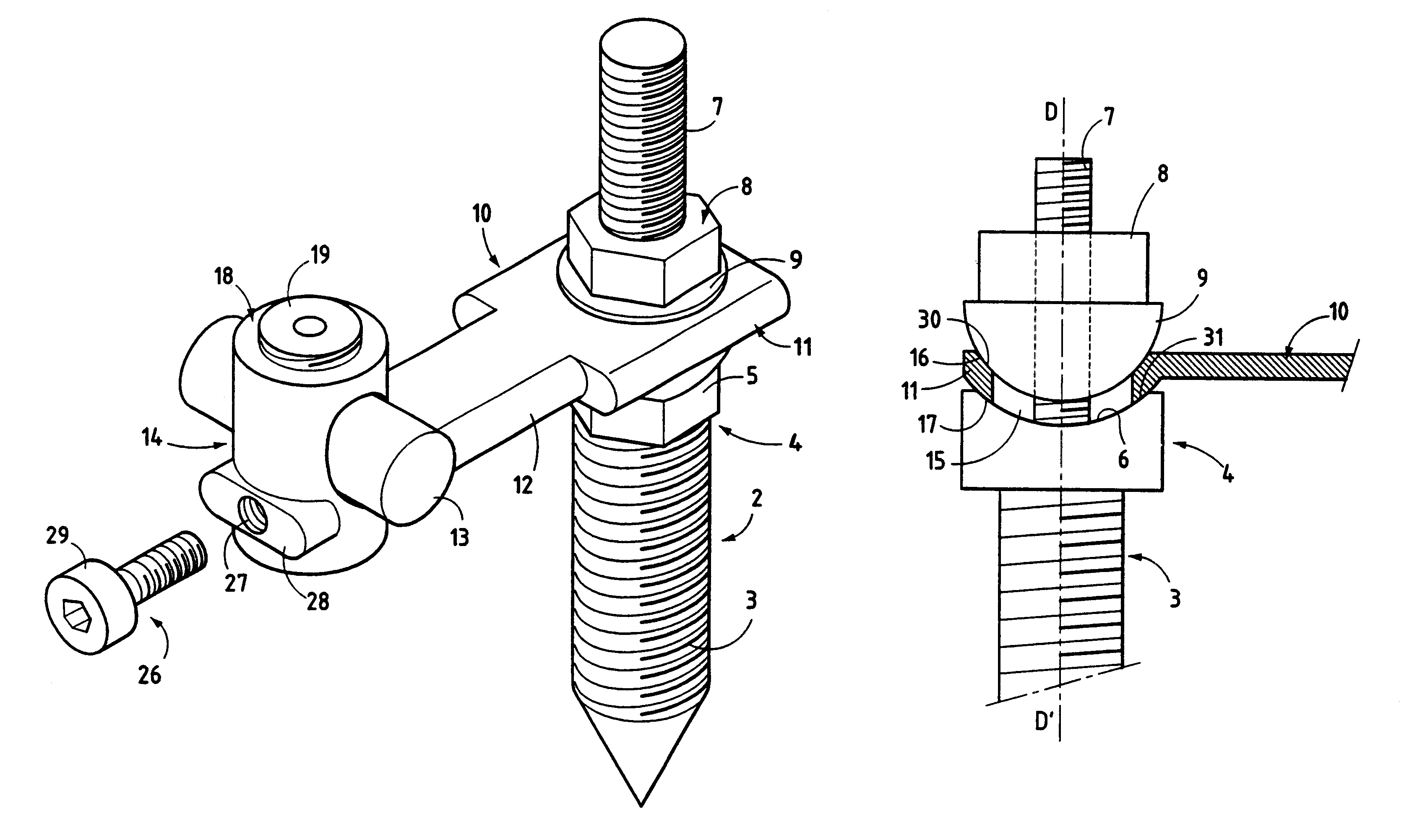
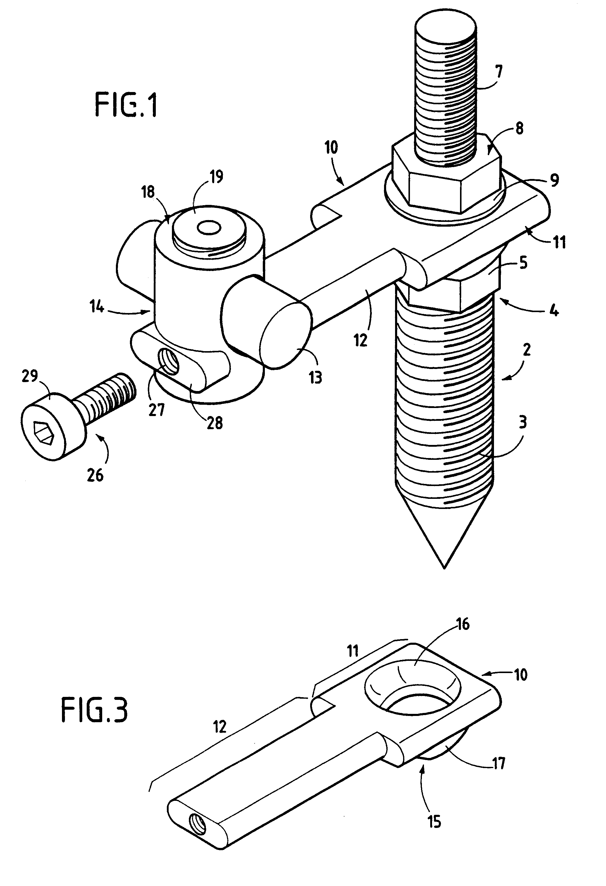
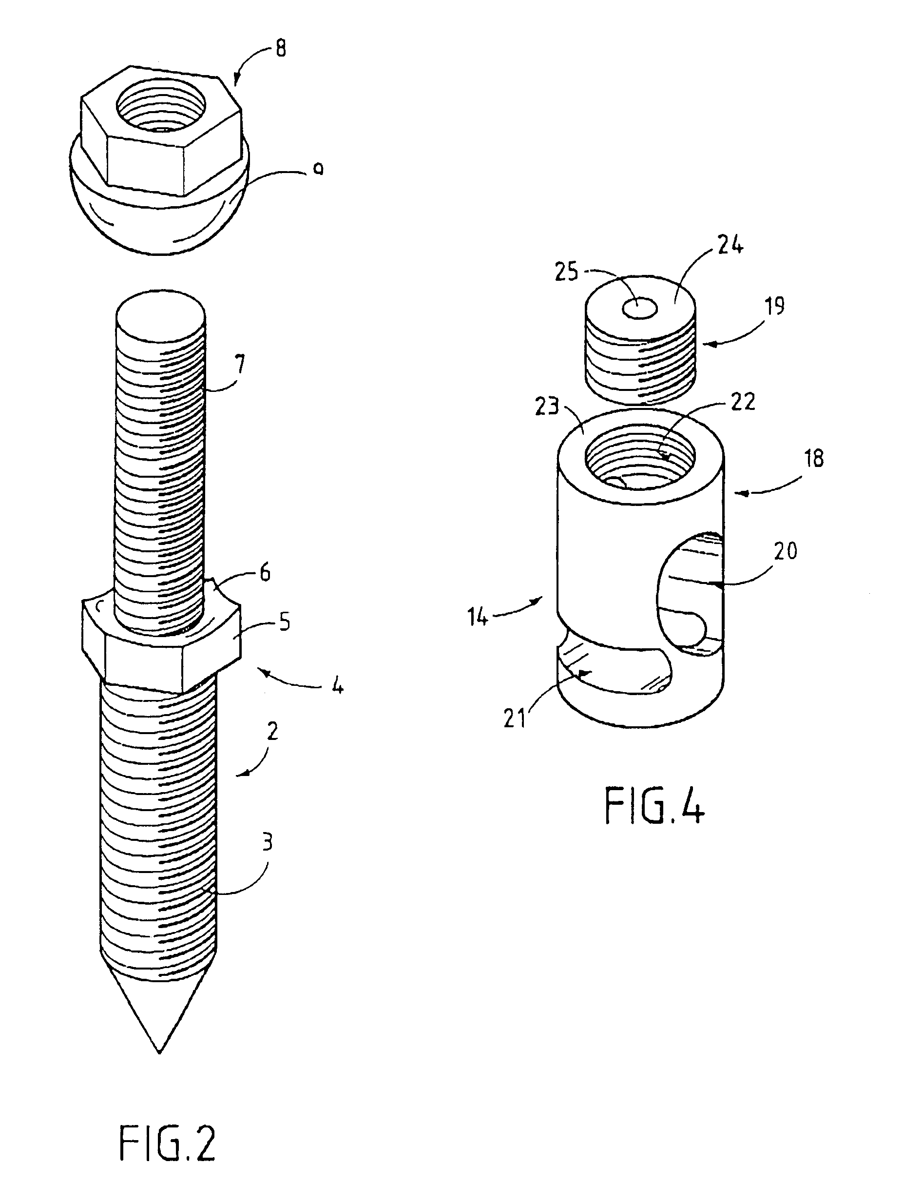
In the invention, the pedicle screw 2 presents a special structure having a first threaded portion 3 at its bottom surmounted by a head 4 with flats 5 and a curved flank ...


PUM


Abstract

The ostheosynthesis connection device of the invention is designed to connect a screw for implanting in the spine to a vertebral support rod. The screw is constituted by a bottom first threaded portion, a head having flats and a curved base, and a top second threaded portion in line with the first. A nut having a curved base is suitable for co-operating with the second threaded portion. For connection with the screw, a connection piece has a hole of inside diameter that is greater than the outside diameter of the second threaded portion of the screw, and around said hole it has curved top and bottom bearing faces such that the connection piece is locked in position relative to the screw once the nut has been tightened by the curved base of the nut bearing against the top bearing face thereof and by the bottom bearing face being clamped against the curved base of the head of the screw.

Description

The present invention relates to a connection device usable in surgical instrumentation of the spine. It relates more particularly to a device suitable for making the connection between screws for securing to a pedicle or to a joint, and a vertebral support rod that is to hold the vertebral column in a given alignment. The instrumentation comprising the screws, the connection device, and the vertebral support rod is used in particular for performing arthrodesis on a segment of the spine.Document EP 0 425 783 discloses such a connection device constituted by a one-sided clamp for fixing a pedicle screw to a vertebral support rod having respective central axes situated in different planes. It is important to be able to vary the inclination of both axes, i.e. both the axis of the vertebral support rod and the axis of each pedicle screw, and,similarly it is important to be able to match the distance between the two axes to the shape desired by the surgeon.In document EP 0 425 783, freed...

Claims


Application Information

Patent Timeline
Patent Type & Authority Patents(United States)
IPC IPC(8): A61B17/70A61B19/00
CPCA61B17/7041A61B2019/307A61B2090/037
Inventor LETENDART, JOELCORDONNIER, DENISDESROUSSEAUX, JEAN-FRAN.CEDILLA.OISSTAHL, PHILIPPEMATHEVON, HENRI
Owner SOCIETE DE GENIE MEDICAL SGM
Why Eureka
Try Eureka