Method and electric motor with rotational stator

a technology of electric motor and stator, applied in the field of electric motor, can solve the problem of limited use of existing electrical motor

Inactive Publication Date: 2002-08-13
CHERCIU TRAIAN
View PDF5 Cites 31 Cited by
  • Summary
  • Abstract
  • Description
  • Claims
  • Application Information

AI Technical Summary

Problems solved by technology

the use of the existing electrical motor is limited by the active torque that ha

Method used


Image

  • Method and electric motor with rotational stator
  • Method and electric motor with rotational stator
  • Method and electric motor with rotational stator

Examples


Embodiment Construction

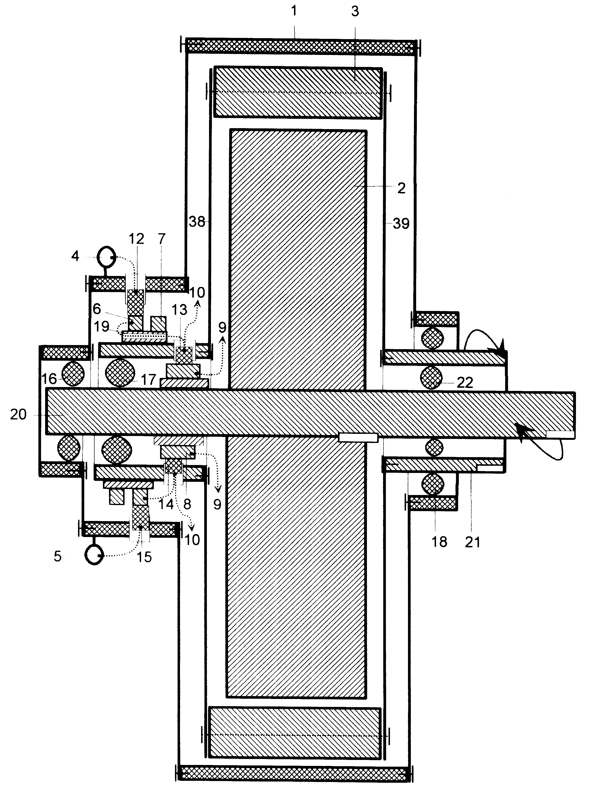
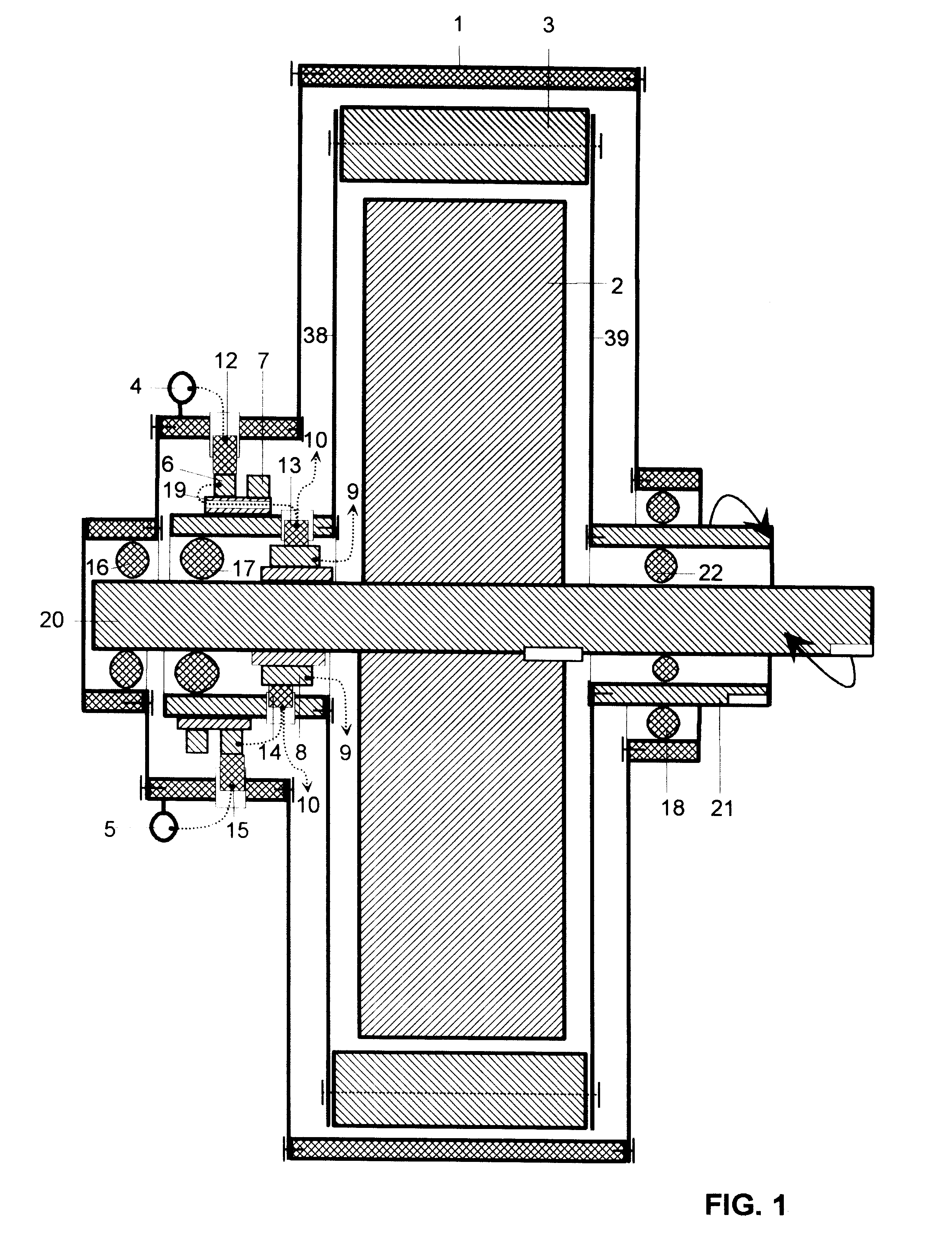
FIG. 1 illustrates only the new and innovative physical components for building the proposed motor and the corresponding electrical diagram: a frame cover 1, a rotor classic coiled 2, a mobile stator classic coiled with rotation in opposite way from the rotor 3, two electrical connectors 4 and 5, two rings rotor 6 and 7 for energization mobile stator coils 10 (not showed), an electrical distributor 8, for energization rotor coils 9 (not showed), two mobile contact brushes 13 and 14 for distributor, two insulating bushes 11 and 19, four bearings 16, 17, 18 and 22, a mechanically coupling axis for one way of rotation 20 and another mechanically coupling axis for opposite way of rotation 21.

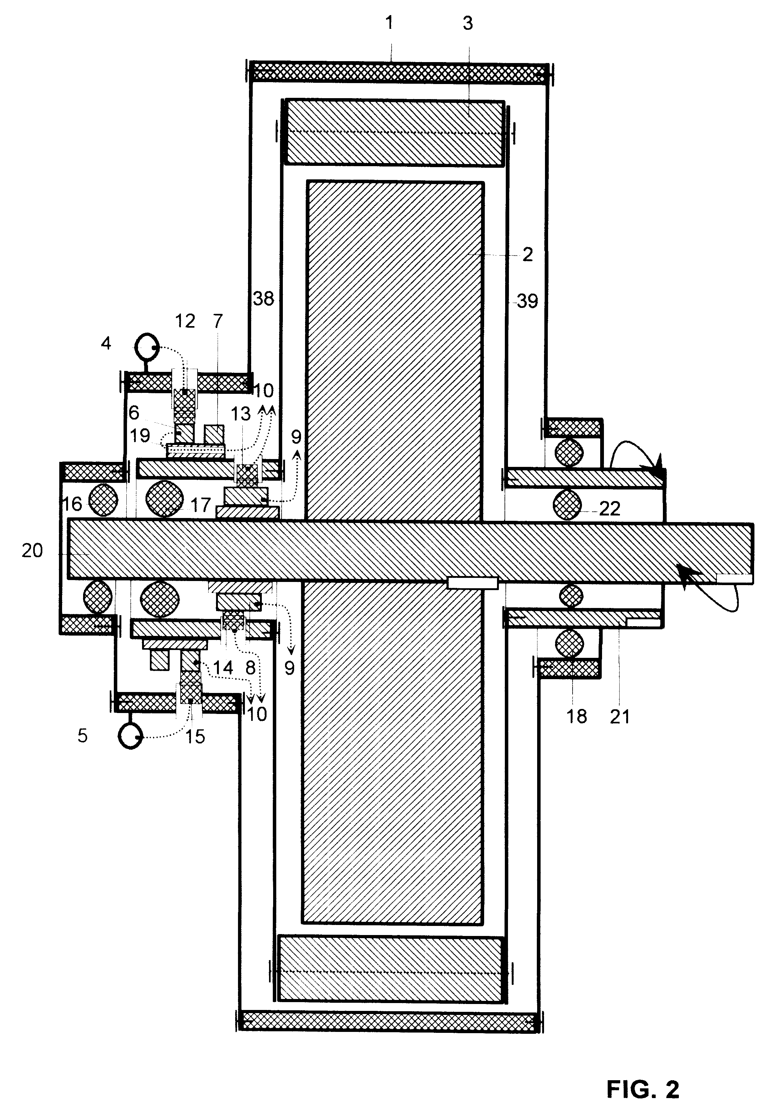
FIG. 2 illustrates the same components as shown in FIG. 1, with the main difference that pertains to energization the motor coils by a A.C. source, thus the new points for coupling of the mobile stator coils are 23 and 24.

FIG. 3 shows an example of a mechanically coupling that can be used on such de...


PUM

PropertyMeasurementUnit
Fractionaaaaaaaaaa
Fractionaaaaaaaaaa
Lengthaaaaaaaaaa

Abstract

An electric composite rotating machine haveing two rotors, capable of developing mechanical power and of runing on two rotational direction at selfadjutable speeds, of differential type, with 40% increase of output, doubling the torque at 30% reduction of used electrical energy.

Description

BACKGROUND OF INVENTIONThis invention concerns an electrical motor to be used in various manufacturing activities and transportation.The existing electrical motor with the coiled stator and coiled rotor that is energized through a distributor, has the following disadvantages:limited output that can not be excceded;the use of the existing electrical motor is limited by the active torque that has only a one way rotational direction;energy waste due to the stationary stator.The first objective is to present the principal elements that differenciate the new electrical motor with mobile stator from the existent electrical motor.The second objective is to describe the governing principle of operation of the new electrical motor.The other objectives are to illustrate the advantages of the new electrical motor.FIG. 1 illustrates the principal parts of the direct current energizing source for new electrical motor with mobile stator.FIG. 2 illustrates the principal components of alternative c...

Claims


Application Information

Patent Timeline
IPC IPC(8): C07K14/435C07K14/715C07K16/18C07K14/705C07K16/28C12N9/64A61K38/00C12N15/09A61K45/00A61K48/00A61P31/12A61P35/00C07K14/47C12N5/10H02K16/00
CPCH02K16/005A61P31/12A61P35/00
Inventor CHERCIU, TRAIAN
Owner CHERCIU TRAIAN
Why Eureka
Try Eureka