Piezoelectric actuator

a technology of actuators and actuators, applied in piezoelectric/electrostrictive device details, piezoelectric/electrostrictive/magnetostrictive devices, piezoelectric/electrostriction/magnetostriction machines, etc., can solve the problem of increasing the number of elements of the circuit, difficult to make the configuration and size of the driving circuit simple and small, and the difficulty of downsizing the driving circuit 104

Inactive Publication Date: 2002-08-13
MINOLTA CO LTD
View PDF7 Cites 34 Cited by
  • Summary
  • Abstract
  • Description
  • Claims
  • Application Information

AI Technical Summary

Problems solved by technology

In the above-mentioned conventional piezoelectric actuator, the charging current and the discharging current are restricted by the constant current circuits, so that a number of elements constituting the circuit inevitably increases.
It becomes difficult to make the configuration and size of the driving circuit simple and small.
In this case, a plurality of circuit elements and switching circuits havin

Method used


Image

  • Piezoelectric actuator
  • Piezoelectric actuator
  • Piezoelectric actuator

Examples


Embodiment Construction

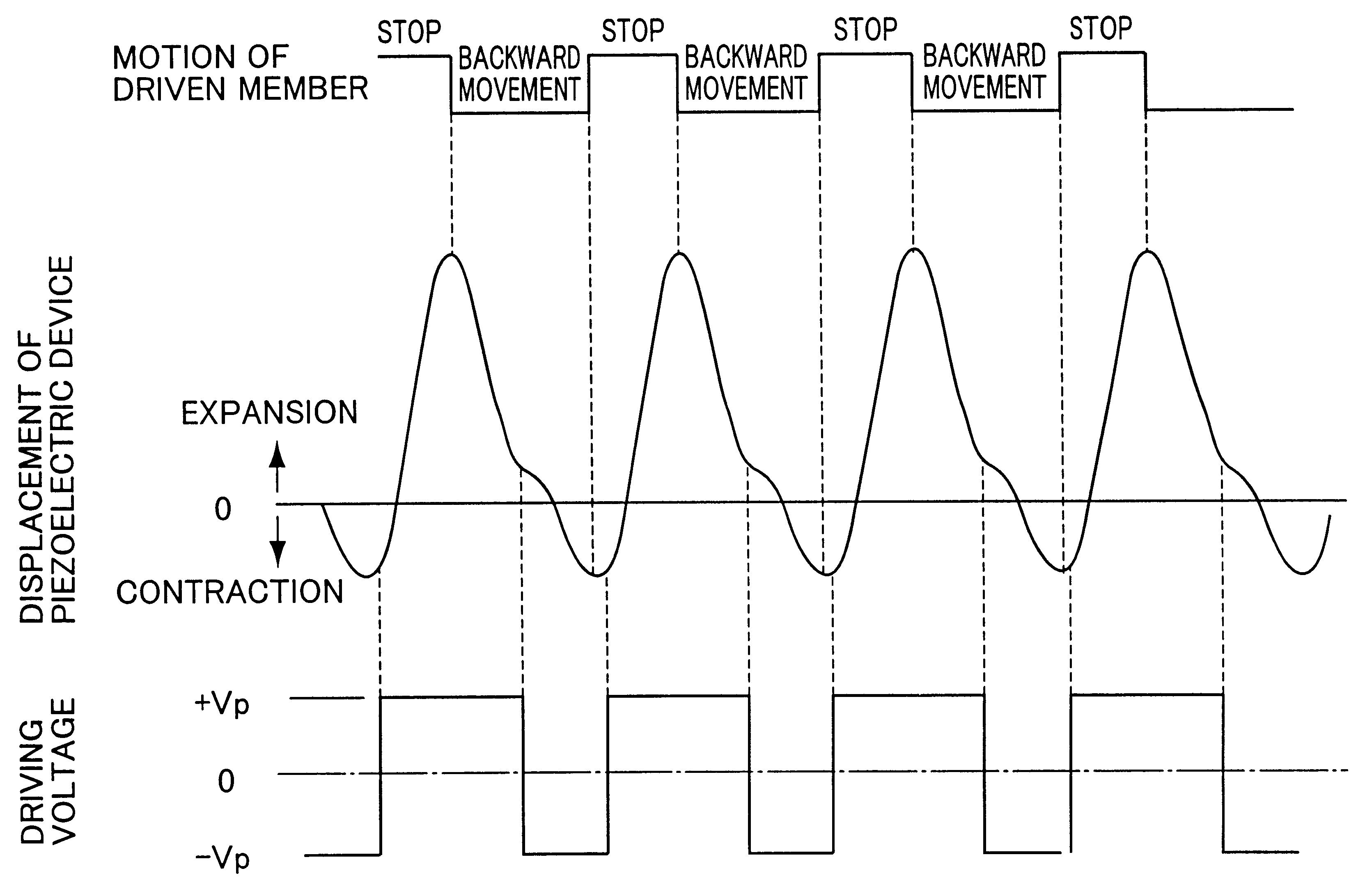
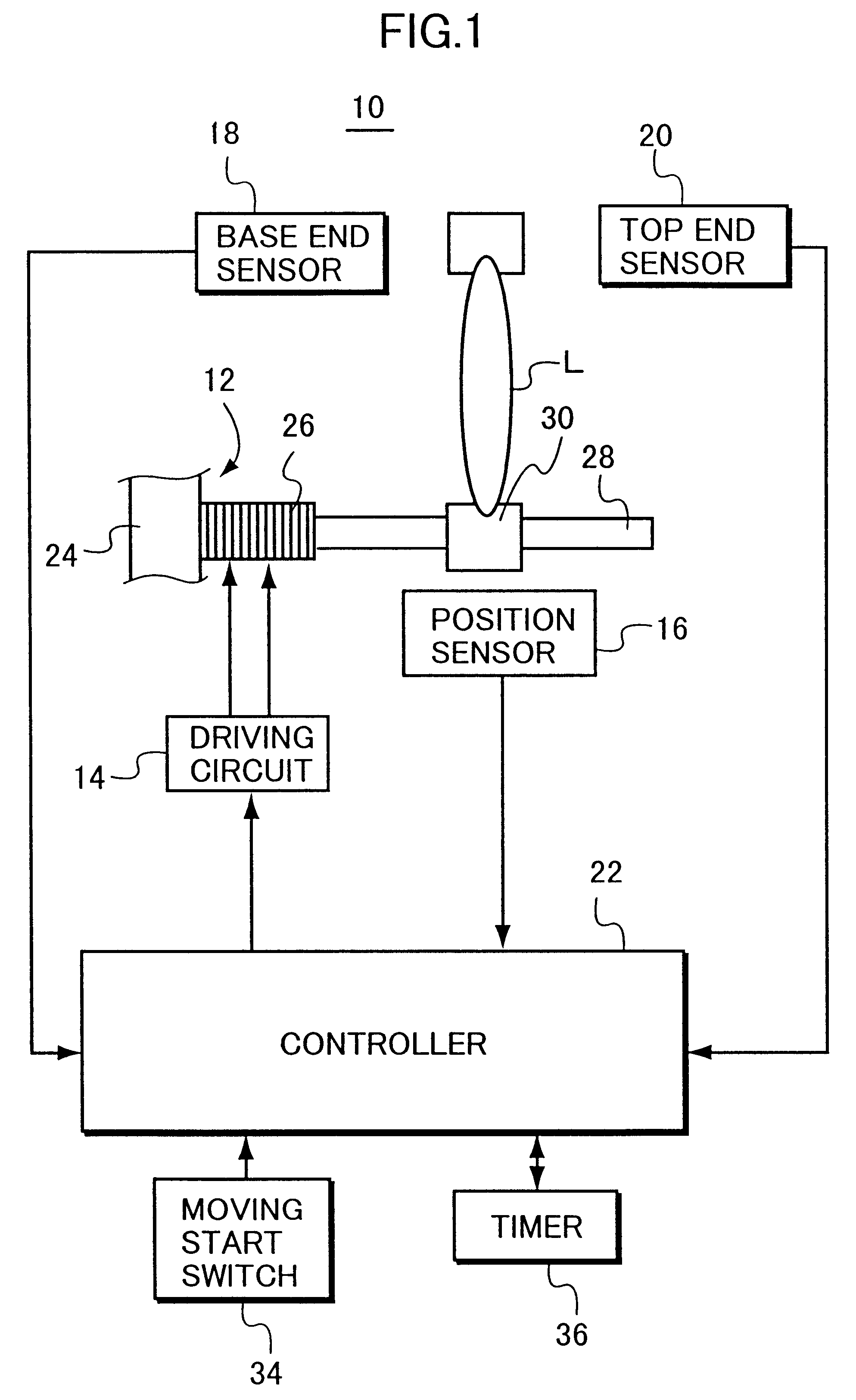
An embodiment of a piezoelectric actuator in accordance with this invention is described. FIG. 1 shows a schematic configuration of an impact type piezoelectric actuator in the embodiment. The piezoelectric actuator 10 comprises a driving unit 12, a driving circuit 14 for driving the driving unit 12, a position sensor 16 for sensing a position of a driven member coupled with the driving unit 12, a base end sensor 18 provided in the vicinity of a base end of the driving unit 12, a top end sensor 20 provided in the vicinity of a top end of the driving unit 12, and a controller 22 for controlling the piezoelectric actuator 10.

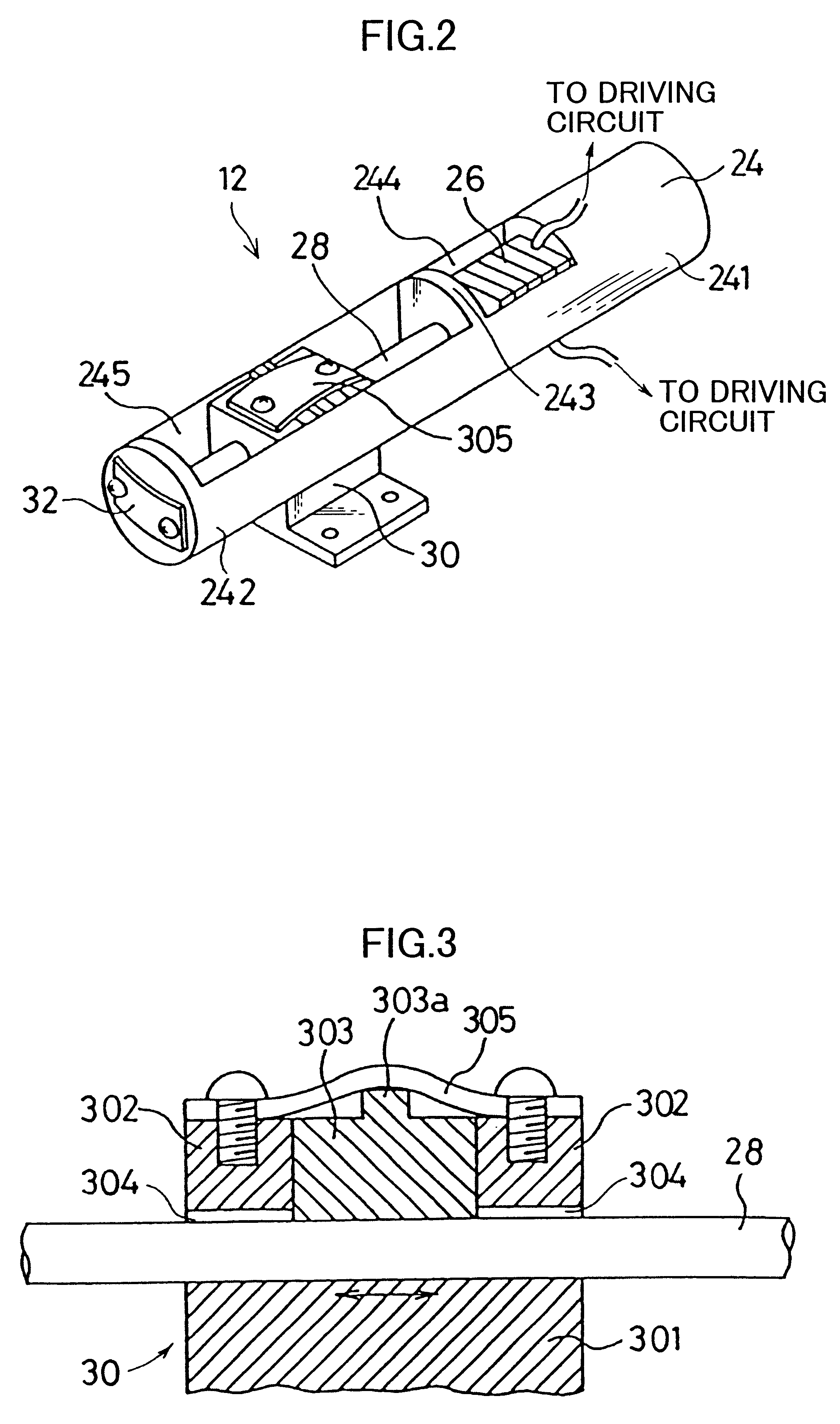
Detailed configuration of the driving unit 12 is shown in FIG. 2. The driving unit 12 is configured by a holder 24, a piezoelectric device 26, a driving member 28, a driven member 30, and so on. The holder 24 for holding the piezoelectric device 26 and the driving member 28 has a first cavity 244 and a second cavity 245 separated by a partition 243. The piezoelect...


PUM


Abstract

In an impact type piezoelectric actuator, a driven member is movably coupled with a driving member by a friction force and the driving member is reciprocally moved by expansion and contraction of a piezoelectric device. The piezoelectric actuator is expanded and contracted by charge and discharge of electric charge thereto. A driving controller controls to vary the charging time period and the discharging time period for changing the expansion speed and the contraction speed of the piezoelectric device, so that the driven member can be moved relative to the driving member.

Description

This application is based on patent application Hei. 11-280180 filed in Japan, the contents of which are hereby incorporated by reference.1. Field of the InventionThis invention relates to a piezoelectric actuator suitable for moving a driven member such as a two-dimensional moving table, a taking lens of a camera, a projection lens of an over-head projector, a lens of a binocular, and so on.2. Description of the Related ArtIn an impact type piezoelectric actuator, a driven member is movably coupled with a rod shaped driving member in an axial direction thereof. An end of the driving member is fixed on an end of a piezoelectric device in a manner so that the polarization of the piezoelectric device coincides with the axial direction of the driving member. For example, U.S. Pat. No. 5,589,723 shows a conventional impact type piezoelectric actuator used for moving a taking lens of a camera.A basic configuration of the conventional impact type piezoelectric actuator is shown in FIG. 20...

Claims


Application Information

Patent Timeline
IPC IPC(8): H01L41/00H01L41/04H02N2/00
CPCH02N2/067H02N2/025
Inventor OKADA, HIROYUKI
Owner MINOLTA CO LTD
Why Eureka
Try Eureka