Optical switching system

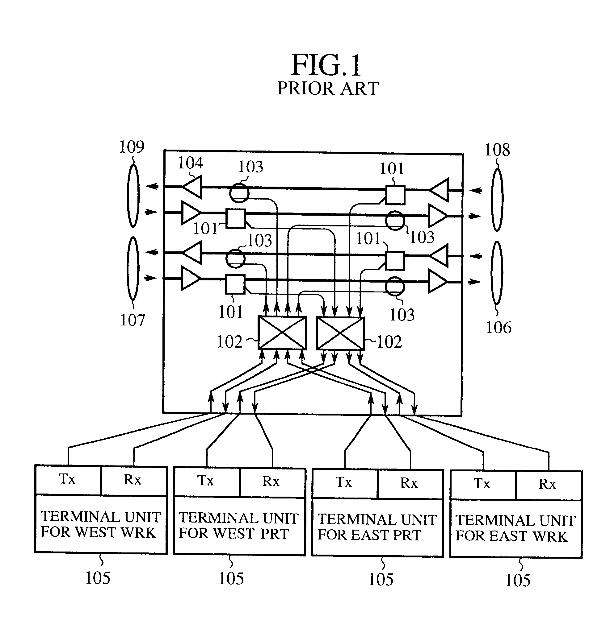
a switching system and optical space technology, applied in the field of optical switching systems, can solve the problems of increasing the packaging dimension of the switch, the working efficiency of the transmission path is limited to 1/2, and the 102 or 117 of the optical space switch utilizing waveguides has not yet reached

Inactive Publication Date: 2002-08-13
KDD CORP
View PDF13 Cites 24 Cited by
  • Summary
  • Abstract
  • Description
  • Claims
  • Application Information

AI Technical Summary

Problems solved by technology

This presents a problem in that the 4.times.4 optical space switches 102 or 117 utilizing waveguides have not yet reached a level required for practical applications in the characteristics such as an extinction ratio or loss, or reliability and power consumption.
These switches, however, have a problem of increasing packaging dimensions because the function of a unit switch is limited to 1.times.2 or 2.times.2, which means that 16 unit switches are required to implement the 4.times.4 optical space switch 102 or 117 by combining the 2.times.2 unit switches.
This presents a problem in that the working efficiency of the transmission paths is limited to 1 / 2 because the network always transmits the same signals through the two paths.

Method used


Image

  • Optical switching system
  • Optical switching system
  • Optical switching system

Examples


embodiment 1

FIG. 4 is a block diagram showing a configuration of an optical switching system in accordance with the present invention. In this figure, the reference numeral 1 designates an input port of a working system (denoted as "WRKin port" from now on) of the present embodiment 1 of the optical switching system; 2 designates an output port of the working system (denoted as "WRKout port"); 3 designates an input port of a preparatory system (denoted as "PRTin port" for now on); 4 designates an output port of the preparatory system (denoted as "PRTout port" from now on); 5 designates an add port of the working system (denoted as "Add(WRK) port" from now on) for inserting in or transmitting to a transmission path a signal through an optical switching system 18; 6 designates a drop port of the working system (denoted as "Drop(WRK) port" from now on) for discarding or receiving a signal from the transmission path through the optical switching system 18; 7 designates an add port of the preparator...

embodiment 2

FIG. 5 is a block diagram showing a configuration of an embodiment 2 of the optical switching system in accordance with the present invention. Incidentally, in the drawings accompanying the following embodiments, the same components as those of the previous embodiments are designated by the same reference numerals, and the description thereof will be omitted.

In FIG. 5, the reference numeral 21 designates a preparatory receiving optical switch for carrying out spatial path switching of the optical signal input from the PRTin port 3, and for supplying a first optical output to the Drop(PRT) port 8; and 22 designates a working received optical signal selector for selecting one of a second optical output of the preparatory receiving optical switch 21 and the optical signal supplied from the WRKin port 1, and for supplying the selected signal to the Drop(WRK) port 6. The reference numeral 23a designates a receiving section including the preparatory receiving optical switch 21 and the wor...

embodiment 3

FIG. 6 is a block diagram showing a configuration of an embodiment 3 of the optical switching system in accordance with the present invention. In this figure, the reference numeral 31 designates a preparatory receiving optical splitter for dividing into two the optical signal supplied from the PRTin port 3; 32 designates a preparatory receiving optical gate installed between a first optical output of the preparatory receiving optical splitter 31 and the Drop(PRT) port 8 for switching between the optical transmissive state and untransmissive state. In the present embodiment 3, the working received optical signal selector 22 is mounted such that it selects one of a second optical output of the preparatory receiving optical splitter 31 and the optical signal supplied from the WRKin port 1, and outputs the selected signal to the Drop(WRK) port 6. The reference numeral 23b designates a receiving section comprising the preparatory receiving optical splitter 31, preparatory receiving optic...


PUM


Abstract

An optical switching system is implemented by providing a transmitting section with a preparatory transmitted optical signal selector and a working transmitted optical signal splitter, which are each implemented by a 1x2 optical space switch, and by providing a receiving section with a receiving optical switch which is implemented by a 2x2 optical space switch, and with a preparatory receiving optical gate which is implemented by a 1x2 optical space switch. This makes it possible to switch between the working system and preparatory system without employing any 4x4 optical space switch, thereby implementing a practical optical switching system without causing such problems as communication interruption during maintenance or impairment of transmission path working efficiency.

Description

This application is the national phase under 35 U.S.C. .sctn. 371 of PCT International Application No. PCT / JP99 / 04682 which has an International filing date of Aug. 30, 1999, which designated the United States of America.1. Technical FieldThe present invention relates to an optical switching system for carrying out path switching on a network that interconnects a plurality of nodes through a working path and a preparatory path using optical signals.2. Background of the InventionFIG. 1 is a block diagram showing a partially redrawn conventionally studied optical switching system as disclosed under the title of "WDM four fiber ring experiment", B-10-230, page 739, Proceedings of the 1997 IEICE (the Institute of Electronics, Information and Communication Engineers of Japan) General Conference; and FIG. 2 is a partially redrawn operational diagram illustrating a path switching operation in case of a fault described in this paper.In FIG. 1, a reference numeral 101 designates an acoustoop...

Claims


Application Information

Patent Timeline
Patent Type & Authority Patents(United States)
IPC IPC(8): H04Q11/00H04B10/03H04B10/032H04B10/27H04B10/275H04B10/29
CPCH04J14/0283H04J14/0291H04J14/0294H04J14/0297H04Q11/0005H04Q11/0062H04Q2011/0024H04Q2011/0043H04Q2011/0081H04Q2011/0092
Inventor UEMURA, ARITOMOICHIBANGASE, HIROSHIMIZUOCHI, TAKASHIKITAYAMA, TADAYOSHIYAMAMOTO, SHUMIYAZAKI, TETSUYAKABASHIMA, TAKATOMIKOBAYASHI, NAOKI
Owner KDD CORP
Why Eureka
Try Eureka