Method for attaching subsea manifold to pipeline tee

a manifold and pipeline technology, applied in underwater equipment, special purpose vessels, borehole/well accessories, etc., can solve the problems of affecting the use of the floor beyond use,

Inactive Publication Date: 2002-08-20
REEL POWER LICENSING
View PDF35 Cites 13 Cited by
  • Summary
  • Abstract
  • Description
  • Claims
  • Application Information

AI Technical Summary

Benefits of technology

A third object of this invention is to provide means for preventing the pipeline connection point for attaching subsea manifolds from flooding before the manifold is attached.
Another object of this invention is to provide means to move sections of a pipeline including valves and tees past rollers on stingers without damaging the rollers.

Problems solved by technology

It is inherent that it would be difficult for a skid package to go over the rollers in a "S" lay stinger.
In addition to interferences with the rollers, there will be interferences with side structures in the pipe lay operations, and the long rigid section implied by the length of the manifold would substantially complicate the associated bending stresses while bending the pipe around the stinger.
If it does not have horizontal tension during laying;, it will buckle as it is laid on the ocean floor and be damaged beyond use.
However, J-Lay towers tend to be more restrictive in size openings to pass manifold skids than the "S" lay barges are.

Method used


Image

  • Method for attaching subsea manifold to pipeline tee
  • Method for attaching subsea manifold to pipeline tee
  • Method for attaching subsea manifold to pipeline tee

Examples


Embodiment Construction

Illustrative embodiments of the invention are described below. In the interest of clarity, not all features of an actual implementation are described in this specification. It will of course be appreciated that in the development of any such actual embodiment, numerous implementation-specific decisions must be made to achieve the developers' specific goals, such as compliance with system-related and business-related constraints, which will vary from one implementation to another. Moreover, it will be appreciated that such a development effort, even if complex and time-consuming, would be a routine undertaking for those of ordinary skill in the art having the benefit of this disclosure.

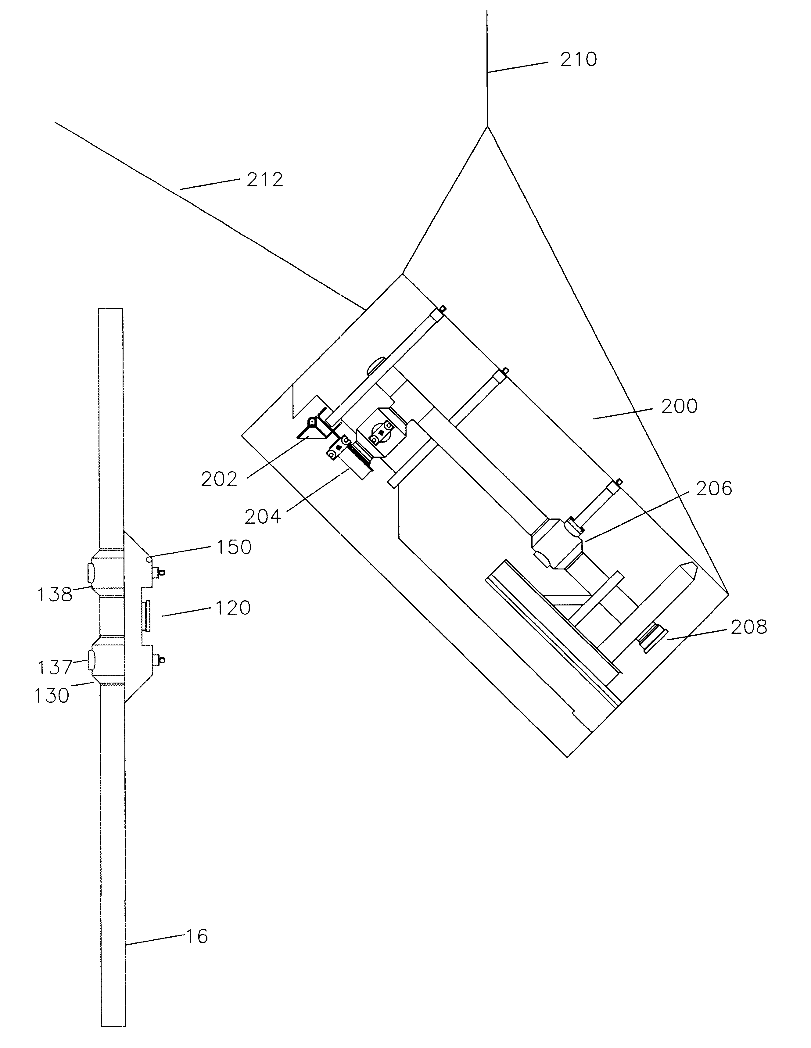
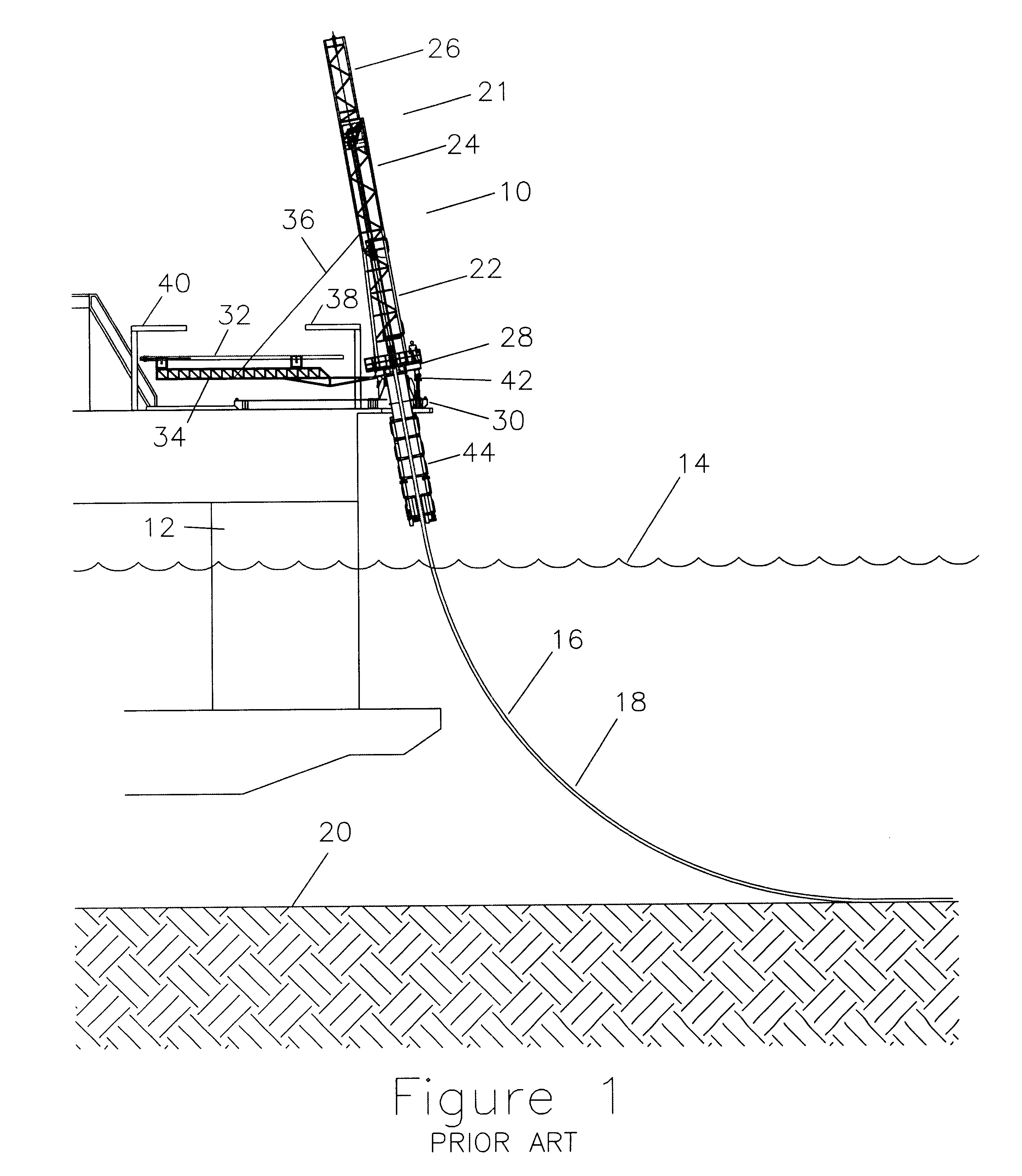
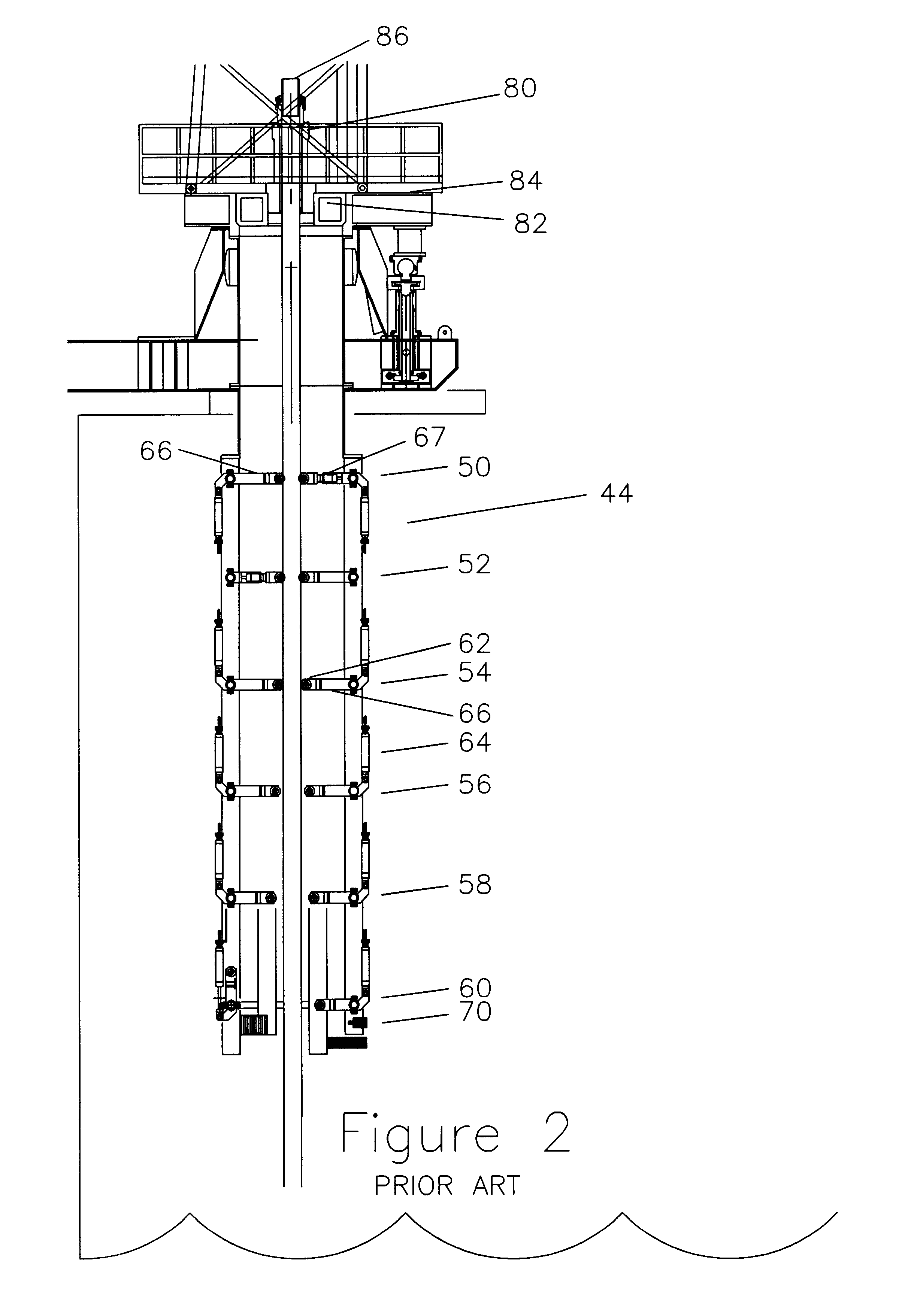
Referring now to FIG. 1, the j-lay tower 10 is shown on a floating vessel 12 in a body of water 14 with a pipeline 16 extending below the j-lay tower 10 around a bend 18 and onto the ocean floor 20. The j-lay tower 10 is shown with a mast 21 including a lower section 22, a middle section 24, and an upp...


PUM


Abstract

A method for attaching subsea manifolds to subsea pipelines which includes attaching a tee member into the pipeline on a vessel, running the portion of the pipeline through support structures which would not pass the manifold, and to an underwater location between the vessel and the ocean floor, then attaching the manifold to the tee section, and then lowering the tee and manifold to the ocean floor.

Description

1. Field of the InventionThis invention relates generally to the inclusion of subsea manifolds while laying underwater pipelines when the inclusion of the manifolds at the conventional work area is made impractical due to space or operational considerations.2. Description of the Related ArtSubsea manifolds are generally rectangular structures with a representative size for discussion being 12 feet wide by 10 feet tall by 25 feet long. In the long direction and approximately 3 feet above the bottom of the skid a main pipeline will pass through the skid. The main pipeline is not usually at the bottom of the skid because the main skid structural beams are at the bottom and any valves in the pipeline would have downward protrusions.Subsea manifolds are typically for the purpose of making connections between short run and long run pipelines on the sea floor. The arrangement of pipelines on the ocean floor looks much like the arrangement of roads on a map. Individual subsea oil or gas com...

Claims


Application Information

Patent Timeline
Patent Type & Authority Patents(United States)
IPC IPC(8): E21B43/00E21B43/01F16L1/26
CPCE21B43/0107F16L1/265F16L1/26
Inventor BAUGH, BENTON F.
Owner REEL POWER LICENSING
Why Eureka
Try Eureka