Electronic locking device

a technology of electronic locking and locking cylinder, which is applied in the direction of transmission, transmission system, indirect connection of subscribers, etc., can solve the problems of difficulty in obtaining a source, etc., and achieves the effect of low cost and simple production

Inactive Publication Date: 2002-08-20
ELECTRONICS KEY SYST E K S R L
View PDF8 Cites 32 Cited by
  • Summary
  • Abstract
  • Description
  • Claims
  • Application Information

AI Technical Summary

Benefits of technology

An of the present invention is to mitigate the above-specified drawbacks by proposing an electronic lock and key assembly that is entirely self-contained, requiring no independent power supply, whether external or in the form of one or more batter

Problems solved by technology

Nevertheless, both the above locks suffer from a major defect that results from the fact that the type of cylinder used is particularly complex to make and is thus very expensive.
As a result, if the key is lost, then it is necessary to replace the cylinder whether or not it is associated with an electronic circuit.
That type of electronically-locked lock nevertheless also suffers fro

Method used


Image

  • Electronic locking device
  • Electronic locking device
  • Electronic locking device

Examples


first embodiment

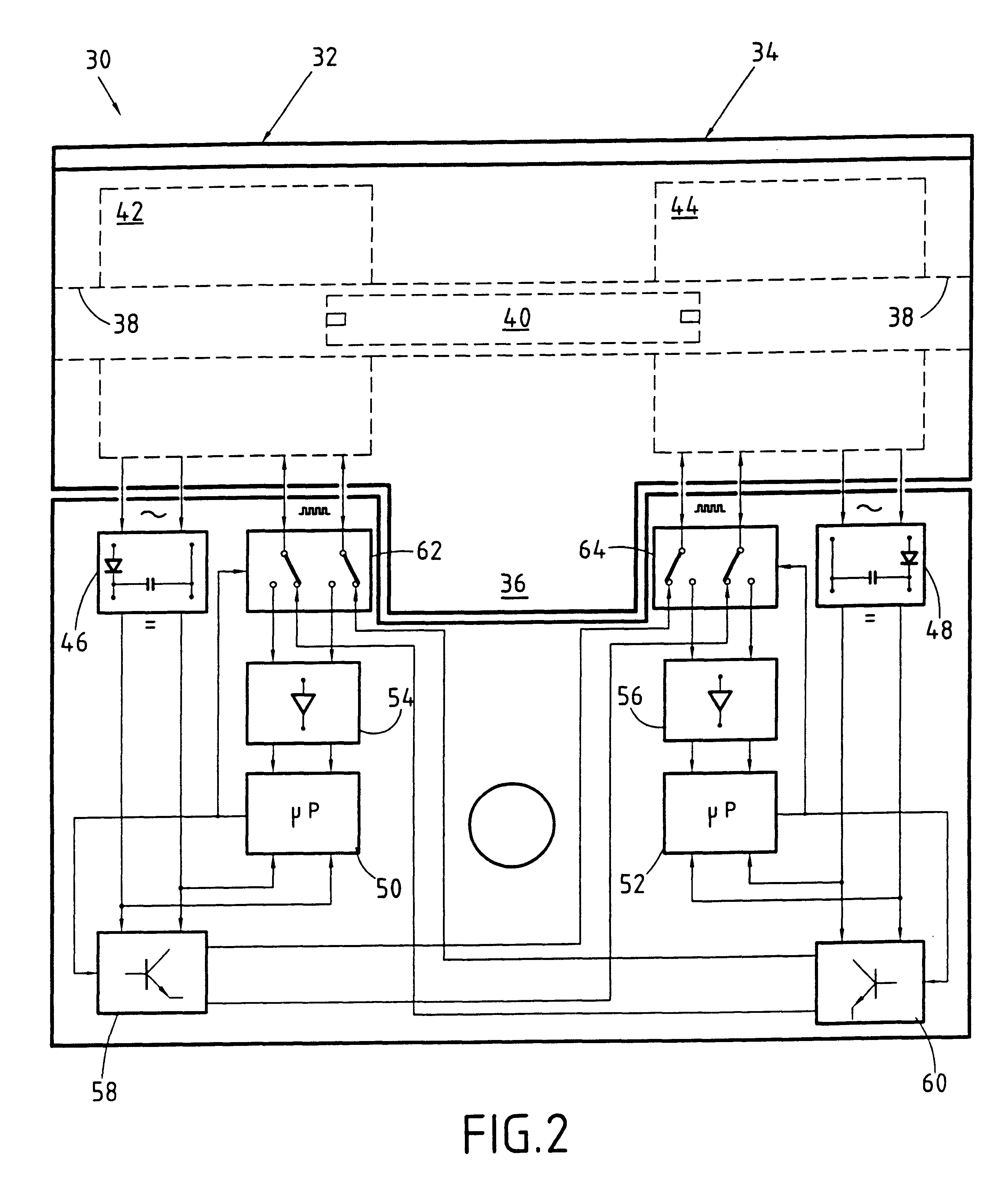
FIG. 2 is a highly diagrammatic longitudinal section through a cylinder 30 of symmetrical European profile having two inlets (two cylinders) of outside shape and size analogous to those of conventional mechanical dual cylinder locks, thereby greatly facilitating replacement, and provided with self-contained power generator means specifically adapted to co-operate with a key of the above-specified type, itself provided with its own power generator means. This dual cylinder lock conventionally has an upstream portion 32, a downstream portion 34, and an intermediate rotary portion or tongue 36 which can be rotated by the key by means of the mechanical second interface means 12 when the key is inserted into either of the two housings 38 of the two cylinders, and providing the identity codes match. The cylinder has moving shutter means 40 constituting a key-expelling piston for preventing any external action being taken on the tongue 36 and for cooperating with the mechanical second inte...

second embodiment

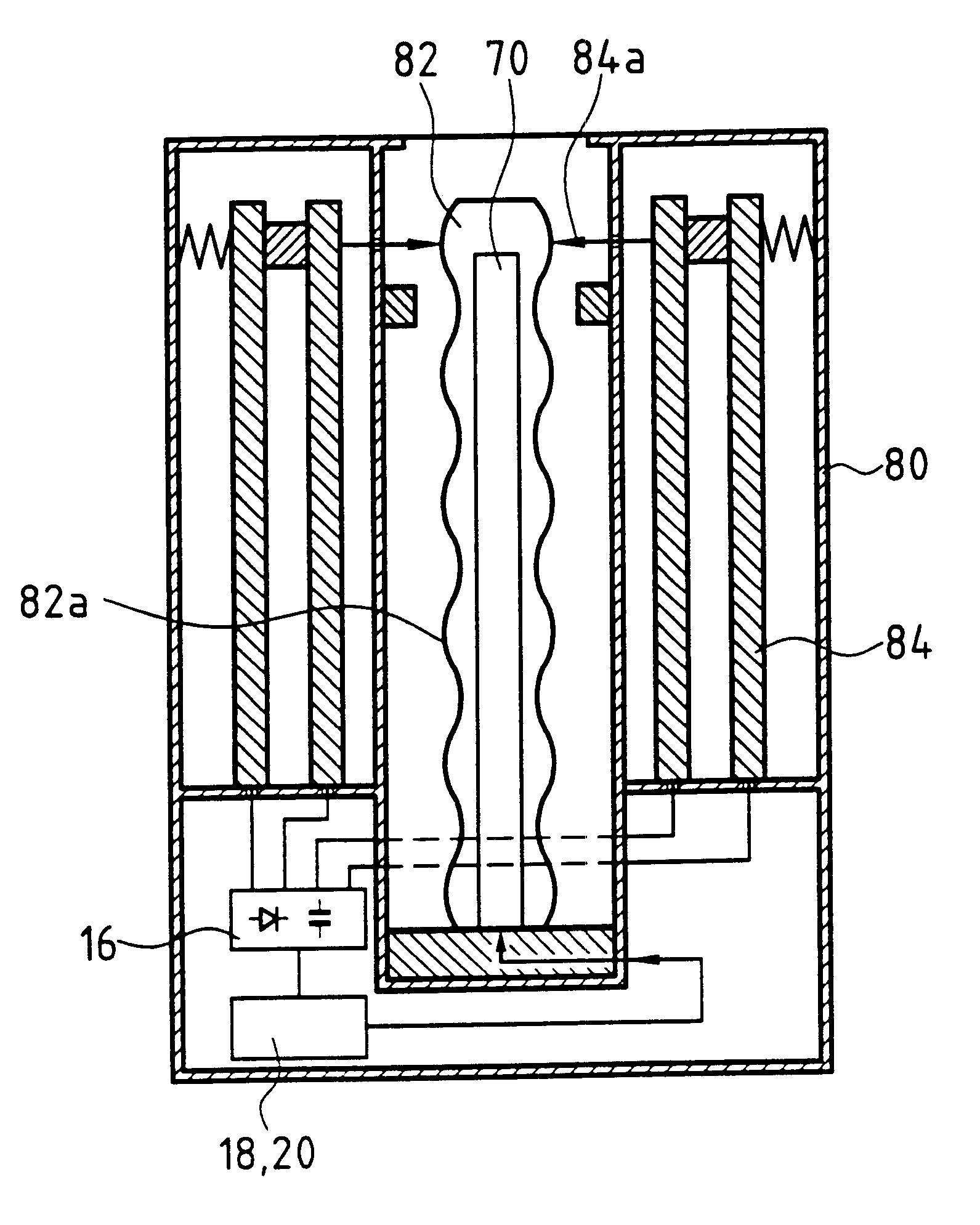
FIG. 13 shows in highly diagrammatic and functional manner the power generator means of the lock and of the key in the form of magnetic elements.

In this embodiment, the power generator means of the lock 42, 44 is constituted merely by a plurality of identical coils, e.g. 90, 92, 94, and 96 conventionally connected in a ring and mounted in a tube of high magnetic permeability, e.g. having a soft iron case 98, and also serving to provide magnetic separation between the coils, the first two coils 90 and 92 being wound in one direction (represented by crosses) while the two immediately following coils 94 and 96 are wound in the opposite direction (with each of their windings being represented by a dot in a circle). A first electrical contact 100 for providing the power link is taken between a first link point between the first and fourth coils 90 & 96 and a second link point is taken between the second and third coils 92 & 94; and a second electrical contact 102 is taken to provide the ...


PUM


Abstract

An electronic key comprising, mounted in a key body, a key shank for insertion into a corresponding housing of a lock cylinder for the purpose of unlocking it, the cylinder having a stator portion and a rotor portion secured to a tongue, and including first mechanical means and first electronic means, and the key including second mechanical means and second electronic means for co-operating with the corresponding first means of the cylinder when the key is fully inserted in the cylinder and for causing the lock to be unlocked when an identity code of the key and a corresponding code of the lock match. The electronic means of the key (16, 18, 20) are powered from self-contained power generator means (14) actuated merely by displacing the key shank in the body of the key.

Description

The present invention relates to the field of electromechanical or electronic keys and locks for preventing access to a given place or for preventing a determined apparatus from being put into operation, for example a rack or cabinet of electronics.PRIOR ARTOver the last few years, locks have been developed that associate mechanical encoding, e.g. implemented in the form of notches, with electronic encoding transmitted between the key and the lock. Patent application EP 0 277 432 shows an example of such an electromechanical lock in which the key comprises not only mechanical encoding for unlocking the lock, but also an electronic circuit which acts, on insertion of the key, to transmit a preprogrammed identity code to the lock. The key is powered from the lock which is itself powered from an external source. Similarly, application FR 2 561 292 discloses an electronic key capable of being used with an electromechanical lock and having both notches for mechanical encoding and an elec...

Claims


Application Information

Patent Timeline
IPC IPC(8): E05B19/00E05B19/04G07C9/00E05B49/00
CPCE05B19/046G07C9/00309G07C9/00944G07C2009/00579G07C2009/00634G07C2009/00777E05B2047/0062E05B49/00
Inventor SIMERAY, JANICK
Owner ELECTRONICS KEY SYST E K S R L
Why Eureka
Try Eureka