Alignment of cathode ray tube displays using a video graphics controller

a video graphics controller and cathode ray tube technology, applied in the direction of television systems, instruments, pulse techniques, etc., can solve the problems of increasing the cost of dynamic adjustment devices, increasing the memory size and processor speed required to facilitate video alignment, and effectively restricting the use of dynamic adjustment techniques to the most expensive crt devices

Inactive Publication Date: 2002-08-20
DISPLAY LAB
View PDF129 Cites 29 Cited by
  • Summary
  • Abstract
  • Description
  • Claims
  • Application Information

AI Technical Summary

Problems solved by technology

As the ability to correct for various types of video distortion characteristics has increased, the memory size and processor speed required to facilitate video alignment has become more expensive and has increased the cost of dynamic adjustment devices.
These costs have effectively limited the use of dynamic adjustment techniques to be employed by only the most expensive CRT devices.
This has limited the use of dynamic adjustment techniques in most CRT monitors manufactured today.

Method used


Image

  • Alignment of cathode ray tube displays using a video graphics controller
  • Alignment of cathode ray tube displays using a video graphics controller
  • Alignment of cathode ray tube displays using a video graphics controller

Examples


Embodiment Construction

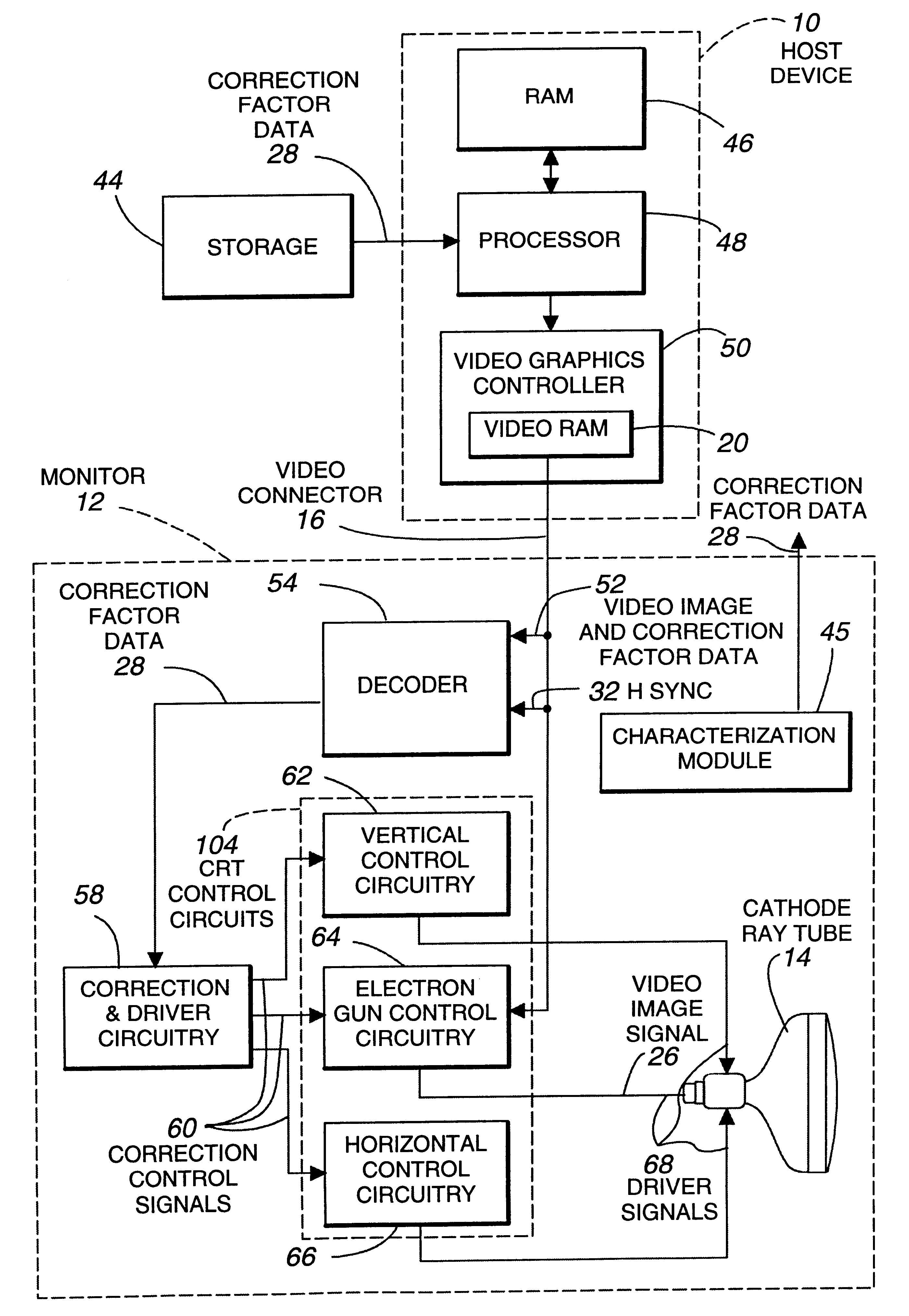
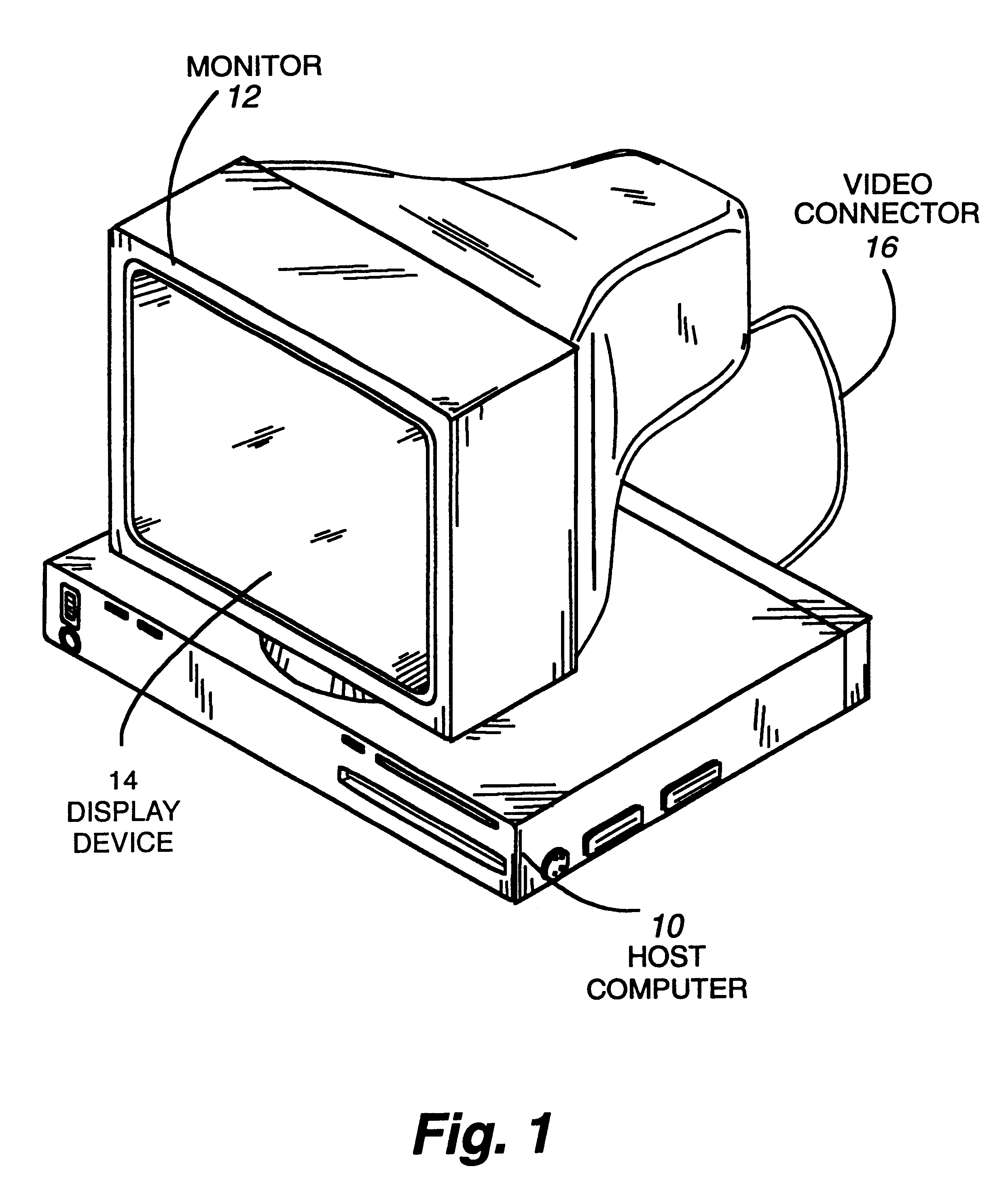
FIG. 1 discloses a host computer 10 and a monitor 12, and its associated cathode ray tube (CRT) 14, that are connected by video connector 16. Numerous and complex interrelationships exist between the various horizontal and vertical correction factor parameters (scan geometries) in cathode ray tube image displays. These relationships can be measured and characterized by correction factor data to automate CRT video image alignment. Correction factor data can be derived as disclosed in U.S. Pat. No. 5,216,204 issued to James R. Webb et al., entitled "Automatic Precision Video Alignment System" that describes the use of a vision system to measure CRT distortion characteristics and also by the interpolation engine disclosed in U.S. patent Ser. No. 08 / 613,902 filed Mar. 11, 1996, entitled "Interpolation Engine for Generating Font Gradients" that can be used to generate additional data points falling between the measured correction data points thus generating additional correction factor d...


PUM


Abstract

Dynamic adjustment techniques for aligning video images in cathode ray tube (CRT) devices are disclosed. A host computer stores correction factor data and video image data in video graphics controller RAM. The host computer processes and transmits the correction factor data, representative of the cathode ray tube distortion characteristics, to the CRT device during the retrace time of the electron beam and video image data during the trace time. The correction factor data may be generated by a vision system, a gain matrix table, interpolation engine or manual methods. Circuitry, within the CRT device, for separating the correction factor data from the video signal is disclosed along with the methods and apparatus used to decode correction data. Data can also be transferred from the monitor back to the host computer over the video connector.

Description

A. Field of InventionThis invention pertains generally to cathode ray tube (CRT) alignment and more particularly to the use of a video graphics controller within a host computer to store and transfer correction factor data to and from a CRT video display.B. Definitions.Address decoder means a device that interprets address information.Align means to cause a video image to be adjusted so that distortion characteristics are reduced and the video image that is displayed on the cathode ray tube forms an image that is pleasing to the eye.Analog decoder means a device that transforms and / or directs an analog signal to a particular channel to produce an analog or digital output signal representative of the analog input signal.Cathode ray tube means a device that is capable of displaying an image using a magnetically deflected electron beam. A cathode ray tube may include one or more of the following: the tube structure, the phosphor screen, the deflection and control windings, including th...

Claims


Application Information

Patent Timeline
Patent Type & Authority Patents(United States)
IPC IPC(8): G09G1/16H04N17/04H04N17/02
CPCG09G1/165G09G1/167G09G2320/08G09G2370/04H04N17/02H04N17/04
Inventor WEBB, JAMES R.SIMPSON, RON C.
Owner DISPLAY LAB
Why Eureka
Try Eureka