Valve flapper with dynamic circumference seal

a valve and dynamic technology, applied in the field of valve assembly, can solve the problems of limiting the speed at which the valve can be operated, increasing the force required to rotate the shaft of the flapper valve, and unable to maintain tight tolerances between the flapper and the inner wall of the passageway, so as to achieve the effect of substantially preventing the flow of fluid through the passageway

Inactive Publication Date: 2002-08-27
MKS INSTR INC
View PDF15 Cites 34 Cited by
  • Summary
  • Abstract
  • Description
  • Claims
  • Application Information

AI Technical Summary

Benefits of technology

The present disclosure, accordingly, provides a valve assembly including a valve body defining a passageway having a longitudinal axis, and a rotatable shaft extending through the body and into the passageway, generally perpendicular to the longitudinal axis of the passageway. A flapper is secured to the shaft within the passageway and movable upon rotation of the shaft between an o...

Problems solved by technology

For a number of reasons, maintaining tight tolerances between the flapper and the inner wall of the passageway can be difficult.
The use of such circumferential o-rings, however, can result in an increase in the force required to rotate the shaft of the flapper valve, and can limit the speed at which the valve can ...

Method used


Image

  • Valve flapper with dynamic circumference seal
  • Valve flapper with dynamic circumference seal
  • Valve flapper with dynamic circumference seal

Examples


Embodiment Construction

The present disclosure provides a valve assembly that beneficially provides both control and shut-off functions. In particular the assembly is designed to control pressure across a wide dynamic range by reducing the closed conductance. The assembly also provides sufficient position resolution near a closed position of the valve to allow control of the reduced conductance. The presently disclosed valve assembly is further designed to be compatible with a wide array of process chemistries and temperatures, last hundreds of thousands of cycles, and be easily replaced in the field.

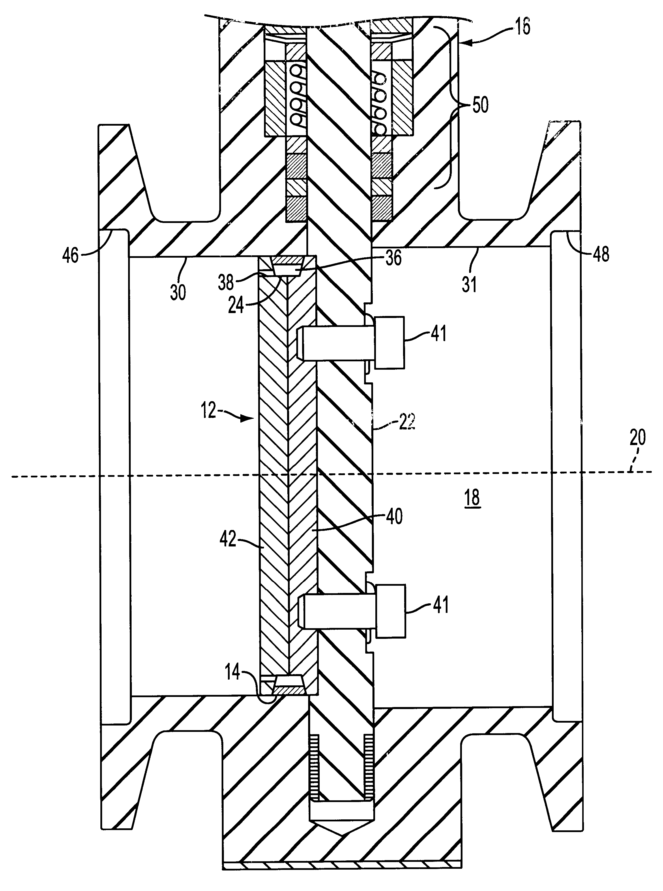
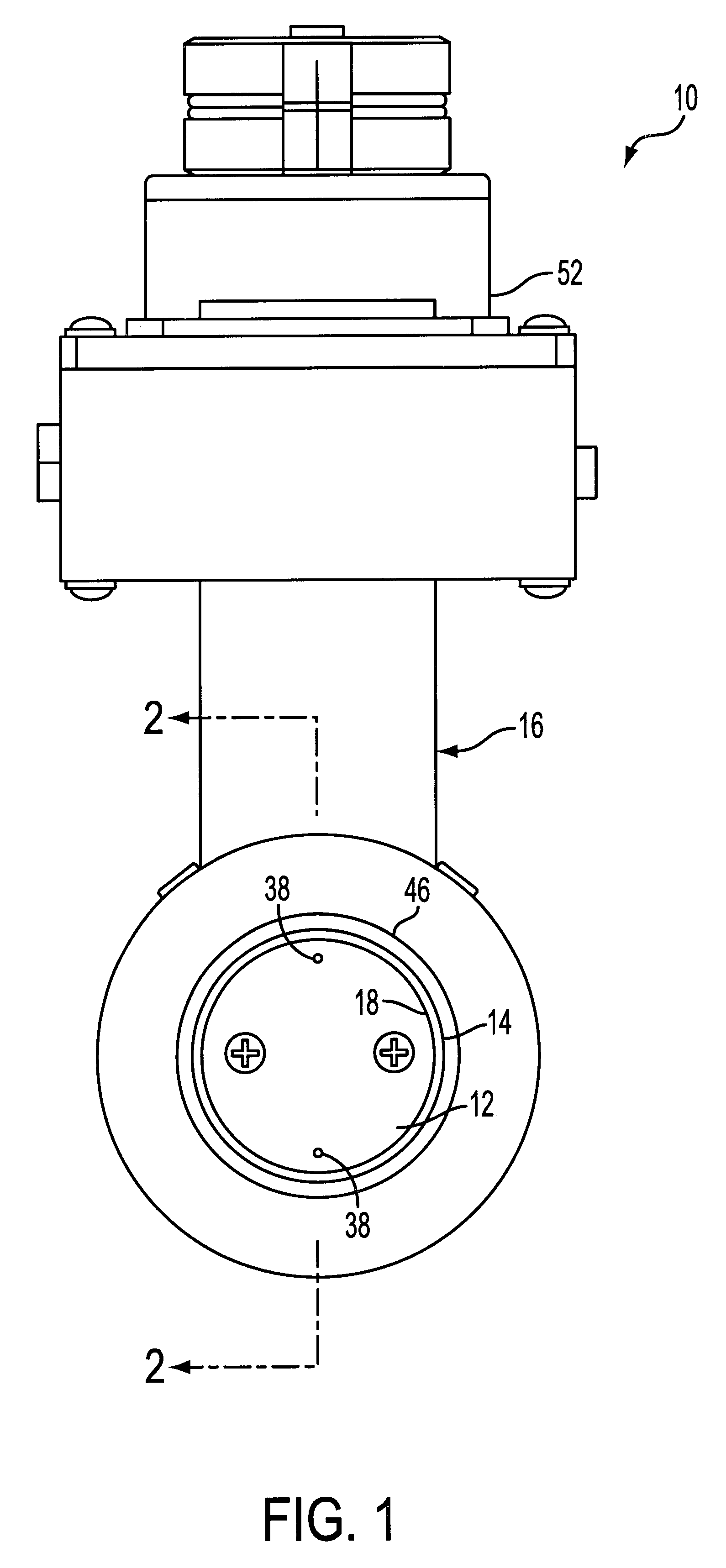
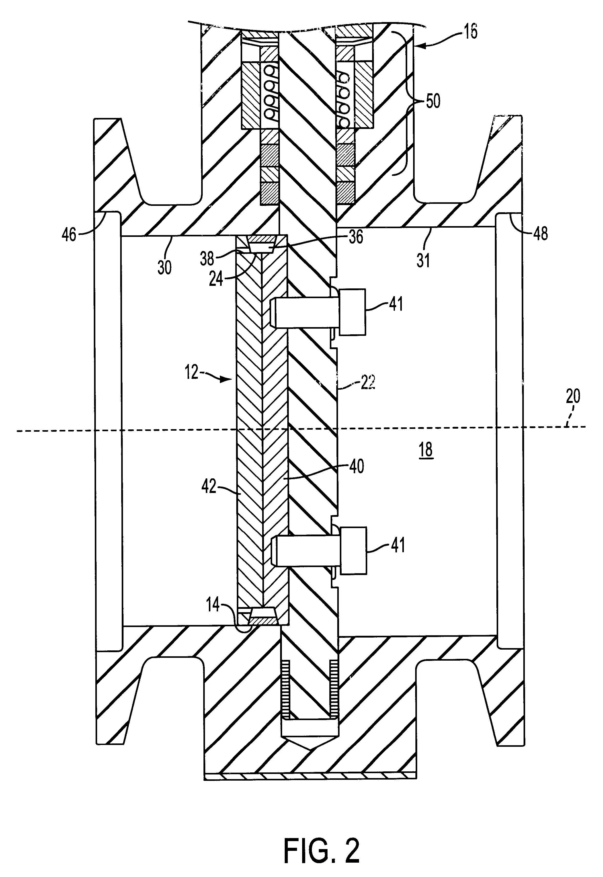
More particularly, the present disclosure provides a valve assembly 10 having a flapper 12 with a dynamic circumference seal 14, as shown in FIGS. 1 and 2. The valve assembly 10 is intended, but not limited, for use in controlling the flow of process gases during a semiconductor chip manufacturing process.

The valve assembly 10 includes a valve body 16 defining a passageway 18 having a longitudinal axis 20, and...


PUM


Abstract

A valve assembly including a body defining a passageway having a longitudinal axis, a rotatable shaft extending into the passageway, generally perpendicular to the axis of the passageway, and a flapper secured to the shaft within the passageway and movable upon rotation of the shaft between an opened position and a closed position. The flapper includes a groove in an outer circumference, and a seal is received in the groove. The seal has an outer circumference greater than the outer circumference of the flapper so the entire outer circumference of the seal contacts a wall of the passageway when the flapper is moved to the closed position. The seal also has an inner circumference greater than an inner circumference of the groove of the flapper such that an enclosed space is defined between the seal and the groove. An aperture provides fluid communication between the enclosed space and the passageway.

Description

FIELD OF DISCLOSUREThe present disclosure relates generally to a fluid valve and, more particularly, to a valve assembly for controlling and shutting off fluid flow. Even more particularly, the present disclosure relates to a valve assembly having a flapper with a dynamic circumference seal.BACKGROUND OF DISCLOSUREA butterfly, or "flapper" valve generally includes a circular, thin flapper-plate coaxially disposed inside a fluid passageway. A rotatable shaft extends laterally into the passageway and is secured to the flapper plate. Examples of flapper valves are show in U.S. Pat. Nos. 5,485,542 and 5,564,679, which are assigned to the assignee of the present disclosure.Rotating the shaft, accordingly, causes the flapper plate to be oriented with respect to the passageway so as to control fluid flow there through. The flapper plate is dimensioned, so that when the shaft is rotated until a plane of the flapper is oriented substantially perpendicular to a longitudinal axis of the passag...

Claims


Application Information

Patent Timeline
IPC IPC(8): F16K1/226F16K1/228
CPCF16K1/2261F16K1/2285Y10T137/0525F16K1/226
Inventor CHAMBERLAIN, DAVID BRIAN
Owner MKS INSTR INC
Why Eureka
Try Eureka