Prosthetic foot

a technology for prosthetic feet and feet, applied in the field of prosthetic feet, can solve the problems of mechanical failure and wear low dynamic response capability of conventional prosthetic feet, and high production and maintenance costs of known prosthetic feet, so as to reduce residual limb to socket shear forces, improve the foot, and improve the effect of foo

Inactive Publication Date: 2002-09-03
BIOQUEST PROSTHETICS
View PDF156 Cites 144 Cited by
  • Summary
  • Abstract
  • Description
  • Claims
  • Application Information

AI Technical Summary

Benefits of technology

The human foot is a complex comprised of twenty-six separate bones. The bones of the foot articulate with one another to create joints. The joints of the foot, through these articulations, allow movement to occur. The motion capability of a particular joint is dependent upon bony articulations, ligamentous reinforcements and muscular control. Motion capability of specific joints of the foot has been studied quite extensively through history. These scientific studies have identified fourteen different axes of rotations of all the joints of the human foot. They have through thoughtful analysis determined how these axes of rotations and motion capabilities function in human gait and running and jumping activities. The prosthetic foot of the present invention has been made in light of these scientific studies with a view toward providing an improved prosthetic foot that mimics the human foot in function in order to provide the amputee with normal human gait characteristics and improve the quality of life of the amputee.
The subtalar joint in the hindfoot portion of the disclosed embodiment constitutes a means for permitting triplanar closed kinetic chain motion of the prosthetic foot in gait. This triplanar motion capability improves the foot staying plantar grade during the stance phase of gait. It also decreases residual limb to socket shear forces associated with motion in the transverse plane.
The plantar surface of the midfoot portion has a longitudinal arch which is formed with a concavity having a longitudinal axis that is deviated in the frontal plane 25.degree.-42.degree. from the transverse plane to create frontal and sagittal plane motion capabilities. The medial aspect of the longitudinal arch concavity is larger in radius and more proximal than the lateral aspect of the concavity. The longitudinal arch is shaped to create a high low dynamic response capability of the foot in gait such that the medial aspect of the longitudinal arch has a relatively higher dynamic response capability and the lateral aspect of the longitudinal arch has a relatively lower dynamic response capability.
The posterior of the forefoot portion of the prosthetic foot includes at least one expansion joint hole extending through the forefoot portion between dorsal and plantar surfaces thereof. An expansion joint extends forward from the expansion joint hole to the anterior edge of the forefoot portion to form plural expansion struts which create improved biplanar motion capability of the forefoot portion. Concavities and convexities are utilized on surface areas of the one piece body of the prosthetic foot with the longitudinal axis orientations thereof being selected to create dynamic response and motion capabilities which mimic the human foot.

Problems solved by technology

These components are sources for mechanical failures and wear.
The known prosthetic feet are also generally expensive to produce and maintain.
None of the conventional prosthetic feet mimic human gait characteristics, e.g., while known designs allow some motion capability, the conventional prosthetic feet do not reflect humanoid characteristics.
The prior art prosthetic feet have not achieved true human gait characteristics because their design features do not mimic the human foot.

Method used


Image

  • Prosthetic foot
  • Prosthetic foot
  • Prosthetic foot

Examples


Embodiment Construction

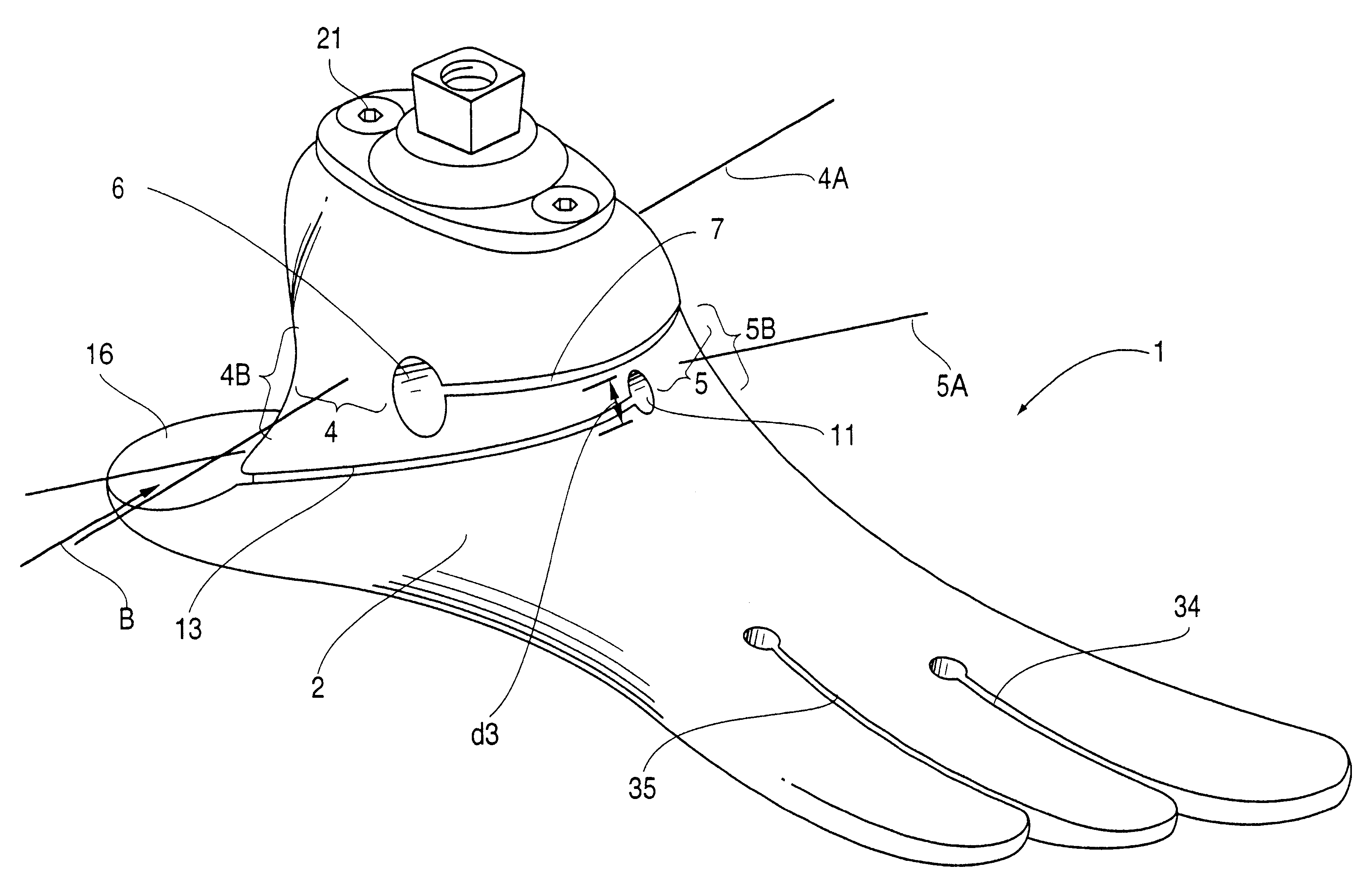
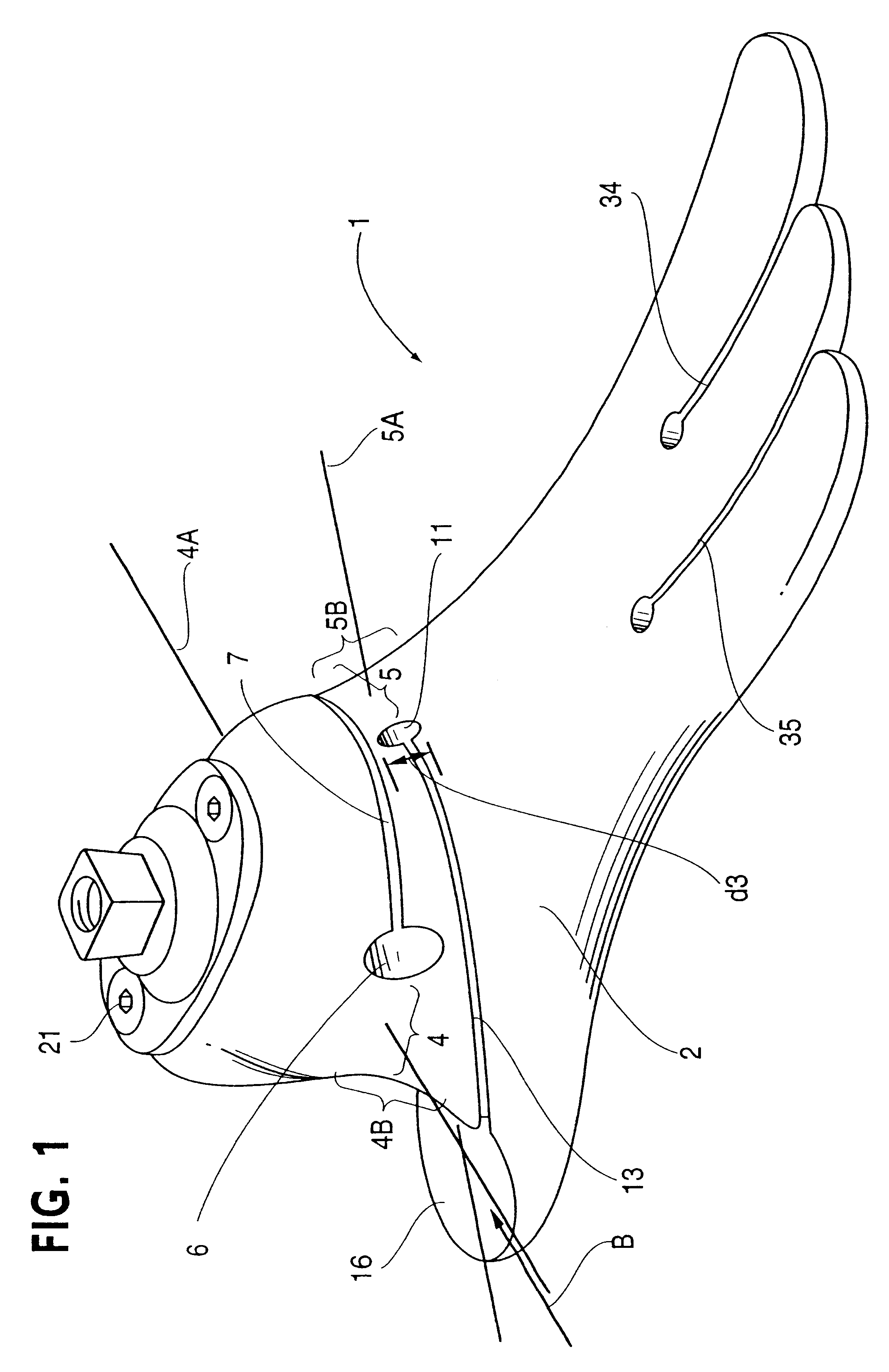
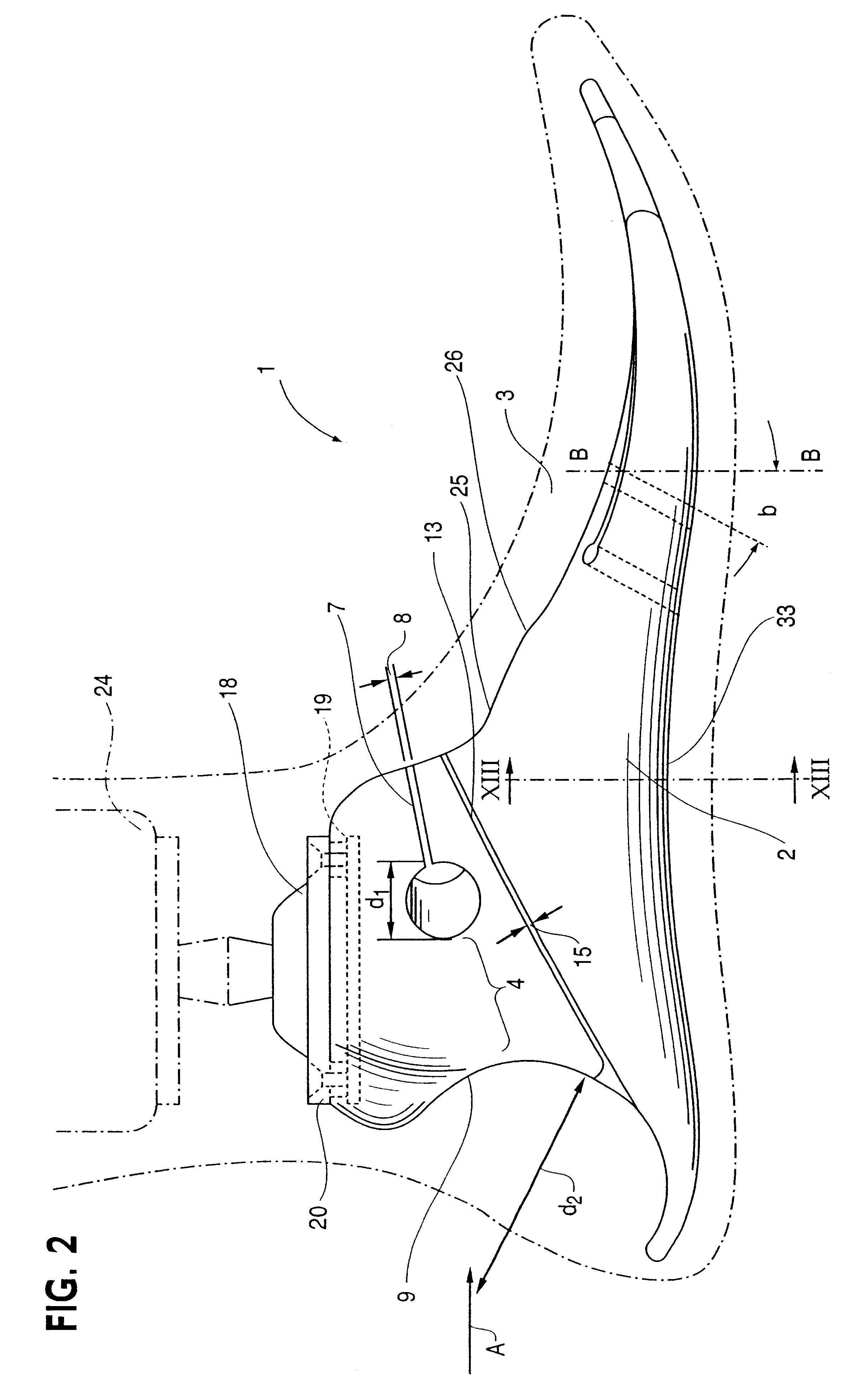
Referring now to the drawings, a prosthetic foot 1 of the invention comprises a body 2 formed of a resilient, semi-rigid material, plastic in the disclosed embodiment, which is formed with forefoot, midfoot and hindfoot portions 2A, 2B and 2C, respectively. A cosmetic covering 3 of the foot surrounds the body 2 as depicted in FIG. 2. The body 2 in the disclosed embodiment is formed by molding or by pouring the material of the body into a negative mold. However, other processes could be employed to form the body 2 such as machining the body from a solid piece of resilient, semi-rigid material, or by using a combination of molding and machining, for example. The plastic of body 2 is an elastomer, polyurethane in the illustrated example but other plastics or composite materials could be used. The body 2 of the foot is shaped and designed to simulate a human foot's hindfoot triplanar, forefoot biplanar and hindfoot, midfoot and forefoot dynamic response windless effect motion capabiliti...


PUM


Abstract

An ankle joint and a subtalar joint provided in a hindfoot permit closed kinetic chain motion of the foot. The ankle and subtalar joints are preferably formed integrally with the hindfoot by respective struts of resilient material of the hindfoot. An arch in the midfoot creates frontal and sagittal plane motion capabilities. The forefoot includes at least one expansion joint hole extending therethrough between dorsal and plantar surfaces. An expansion joint extends forward from the hole to the anterior edge of the forefoot to form plural expansion struts that create improved biplanar motion capability of the forefoot. Concavities and convexities on the surface of the hindfoot, midfoot and forefoot encourage desired motions and motion directions so that the foot functions and feels like a normal foot to the amputee.

Description

A prosthetic foot that mimics the human foot in function is disclosed. The prosthetic foot has hindfoot triplanar motion capability, biplanar midfoot and forefoot motion capabilities and high low dynamic response characteristics for improving gait and comfort qualities of the amputee in walking, running and jumping activities.BACKGROUND AND SUMMARYThose in the field of prosthetics have in the past manufactured prosthetic feet which permit varying degrees of motion capability. Most of the known prosthetic feet utilize metal hinges with rubber bumpers to enable this motion capability. These components are sources for mechanical failures and wear. The known prosthetic feet are also generally expensive to produce and maintain. None of the conventional prosthetic feet mimic human gait characteristics, e.g., while known designs allow some motion capability, the conventional prosthetic feet do not reflect humanoid characteristics. These characteristics relate to the biomechanical function ...

Claims


Application Information

Patent Timeline
Patent Type & Authority Patents(United States)
IPC IPC(8): A61F2/66A61F2/60A61F2/00A61F2/50
CPCA61F2/66A61F2/6607A61F2002/5001A61F2002/6621A61F2002/6642A61F2002/665
Inventor TOWNSEND, BARRY W.CLAUDINO, BYRON KENT
Owner BIOQUEST PROSTHETICS
Why Eureka
Try Eureka