Dental impression tray

a dental impression and tray technology, applied in the field of dental impression tray, can solve the problems of different trays used, the overall cost of the dental impression tray, and the rigid sidewalls of the dental impression trays that are sometimes bent outwardly during patient occlusion, so as to reduce the cross-sectional area segment and minimize any spring back

Inactive Publication Date: 2002-09-17
ADVANTAGE DENTAL PRODS
View PDF6 Cites 22 Cited by
  • Summary
  • Abstract
  • Description
  • Claims
  • Application Information

AI Technical Summary

Benefits of technology

Preferably, the material extending between the sidewalls comprises polycaprolactone which becomes pliable above about 140.degree. F. The polycaprolactone thus enables a bite trace to be easily formed in the rigid layer by simply heating the tray prior to taking the dental impression.
In the preferred embodiment of the invention, a frame secured to the sidewalls extends around the end of the rigid layer opposite from its outwardly protruding portion. This frame, which preferably is of one-piece construction with the sidewalls, includes at least one reduced cross-sectional area segment intermediate its ends and optionally the frame may be used in lieu of the sidewalls. This reduced cross-sectional area segment minimizes any spring back between the dental impression tray sidewalls that may occur while taking the dental impression.

Problems solved by technology

One disadvantage of these previously known dental impression trays, however, is that different trays were used in dependence upon whether a half arch or three-quarters arch dental impression was required.
This necessarily increased the tooling for the dental impression trays and thus the overall cost of the dental impression tray.
A still further disadvantage of these previously known dental impression trays is that, upon occlusion, the rigid sidewalls of the dental impression trays occasionally bent outwardly during patient occlusion.
Due to the rigidity of the tray, however, upon removal of the tray with the formed impression, the tray would "spring back" to its original shape so that the impression formed in the dental impression material did not precisely conform to the patient's bite.
Consequently, the bridgework typically formed from the dental impression would oftentimes require time-consuming modification by the dentist in order for the bridgework to properly fit in the patient's mouth.
Indeed, in some cases, such modification of the bridgework was not even possible so that it was necessary to take the dental impression and reform the dental bridgework.

Method used


Image

  • Dental impression tray
  • Dental impression tray
  • Dental impression tray

Examples


Embodiment Construction

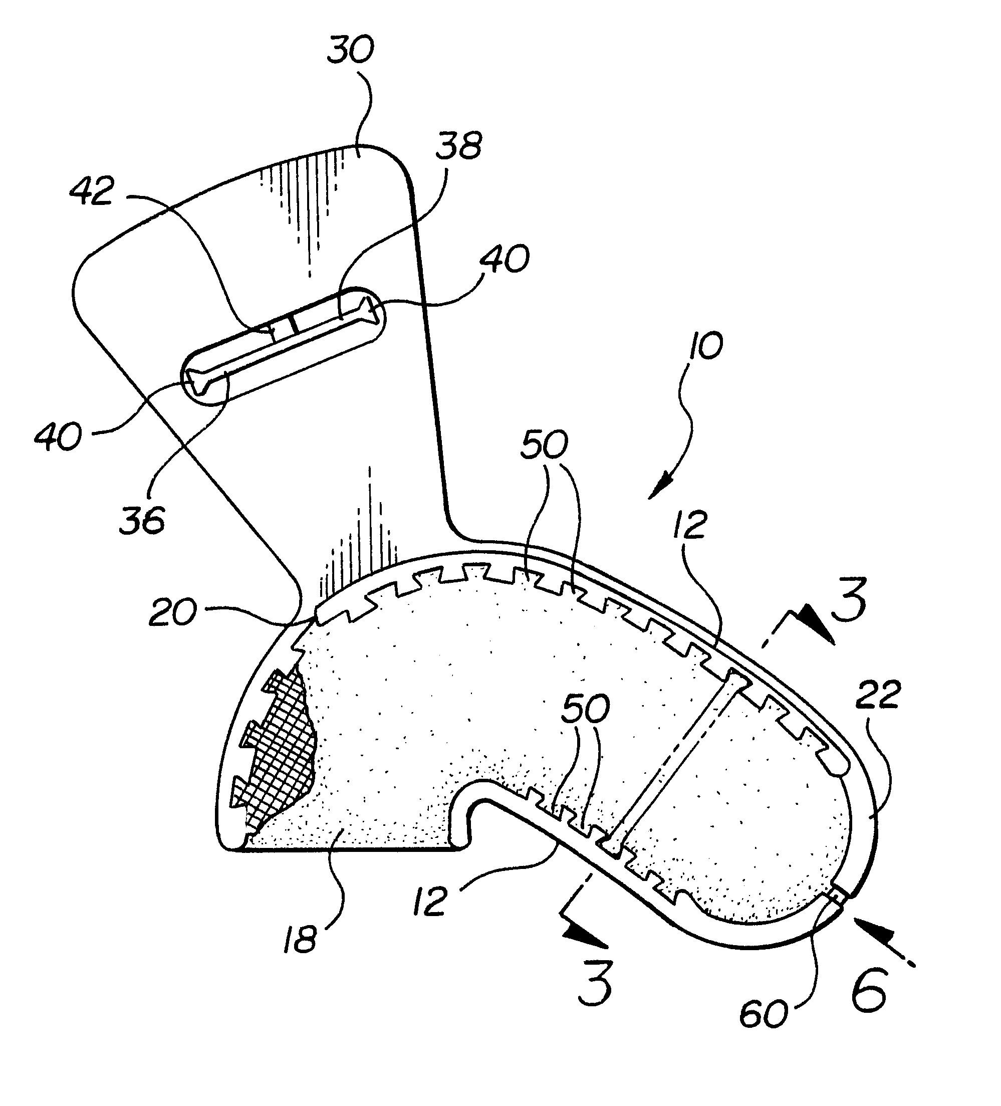
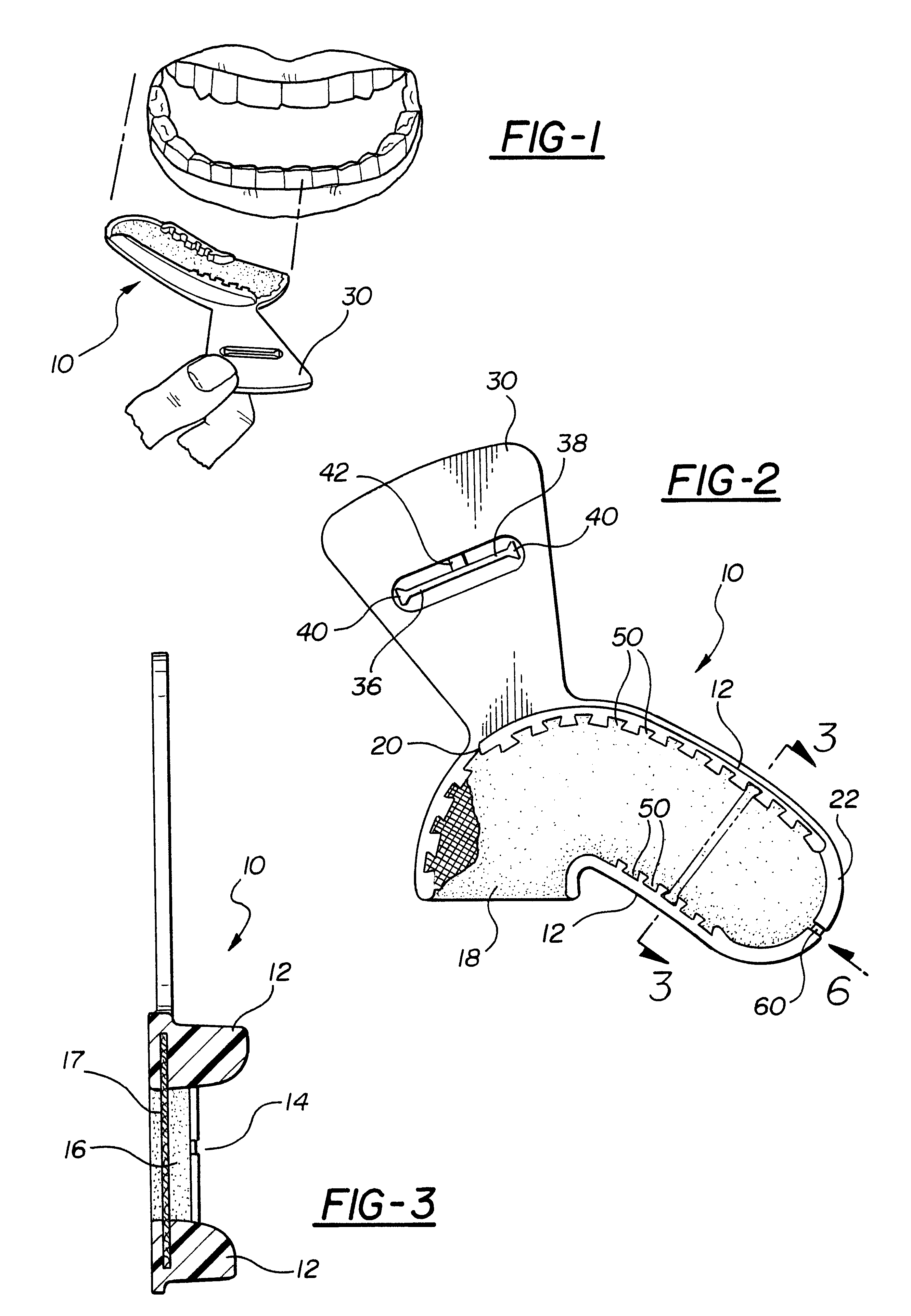
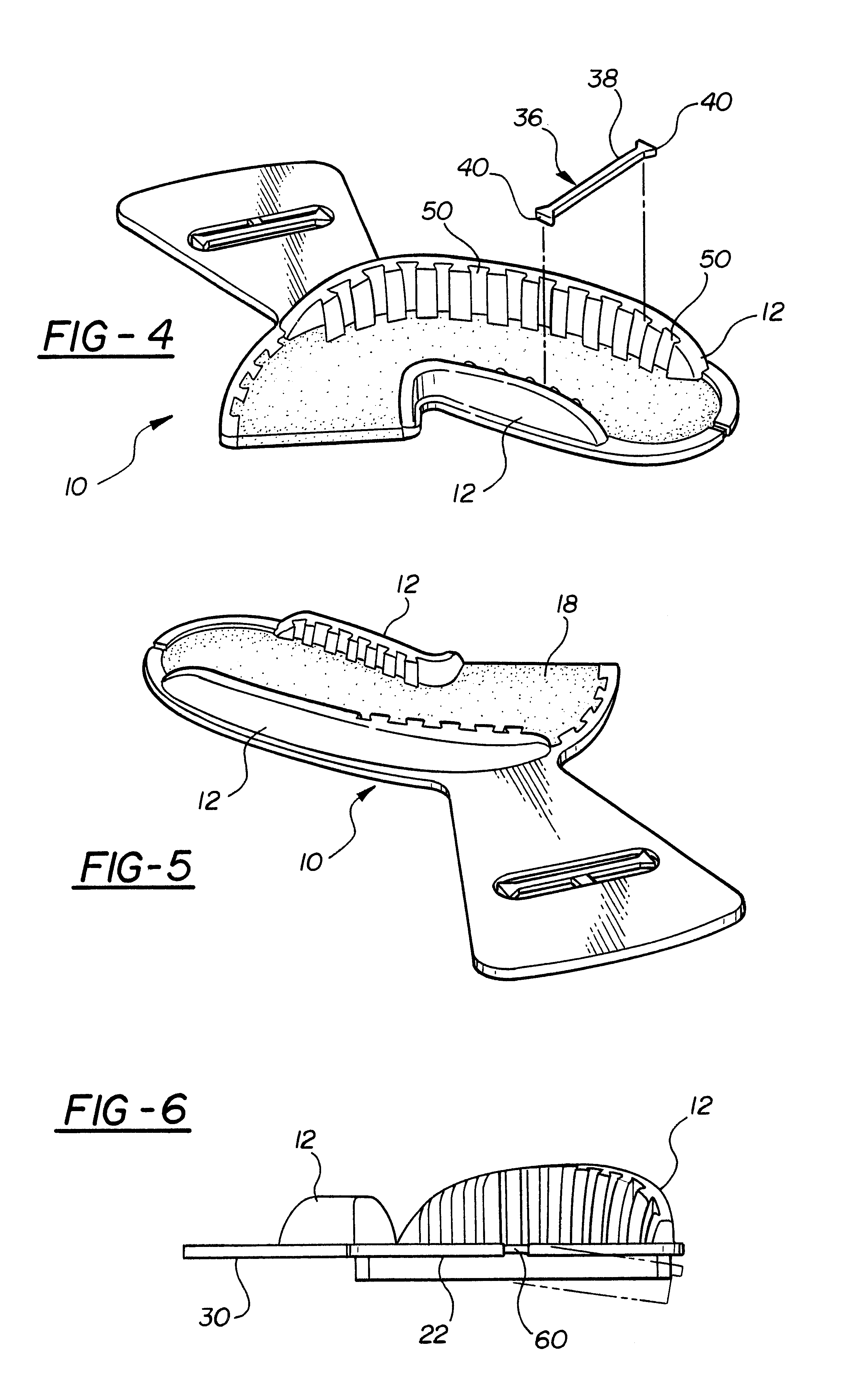
With reference first to FIGS. 2 and 3, a preferred embodiment of the dental impression tray 10 of the present invention is there shown and comprises a pair of sidewalls 12 which are spaced apart and generally parallel to each other and form a channel 14 therebetween. The sidewalls 12, furthermore, are dimensioned to extend substantially a one-half arch of a dental occlusion, i.e. along one-half of a patient's bite. The sidewalls 12 also preferably flare outwardly from each other thereby avoiding contact with the patient's gums while minimizing the amount of dental impression material necessary to make an impression.

Still referring to FIGS. 2 and 3, a layer 16 of material extends between the sidewalls 12 and, together with the sidewalls 12, forms a generally U-shaped channel 14 therebetween. The layer of material 16, furthermore, preferably comprises polycaprolactone which becomes pliable above about 140.degree. F. Other materials, however, such as wax, may alternatively be used. A g...


PUM


Abstract

A dental impression tray having a pair of spaced and outwardly flared sidewalls with a layer of material, such as gauze, netting, plastic or the like, or a rigid material, extending perpendicularly between the sidewalls. The sidewalls, furthermore, are dimensioned to extend substantially a one-half arch of a dental occlusion. The layer of material, however, extends outwardly from one end of the sidewalls so that the layer extends substantially a three-quarters of an arch of a dental occlusion. The dental impression tray is easily convertible between a one-half arch and a three-quarters arch of a dental occlusion by selectively removing the outwardly extending portion of the layer material. Additionally, a frame connects the sidewalls together while a notch in the frame enables the sidewalls to deflect upon occlusion and remain in a deflected position. Optionally, the sidewalls are eliminated.

Description

I. Field of the InventionThe present invention relates generally to a dental impression tray.II. Description of Related ArtDental impression trays, such as the dental impression tray disclosed in my earlier U.S. Pat. No. 4,619,610, are conventionally used to form dental impressions. These previously known dental impression trays typically comprise a pair of spaced sidewalls having a layer of rigid material extending between the sidewalls so that the sidewalls, together with the layer of rigid material, or optionally a gauze layer, netting, plastic or the like, form a channel.In order to form the impression, the channel of the dental impression tray is filled with an impression material, such as silicon, and the patient occludes against the rigid material. Once the dental impression material has set, the impression tray together with the now set impression material is removed from the patient's mouth.These previously known dental impression trays are typically manufactured in either ...

Claims


Application Information

Patent Timeline
Patent Type & Authority Patents(United States)
IPC IPC(8): A61C9/00
CPCA61C9/0006
Inventor PELERIN, JOSEPH J.
Owner ADVANTAGE DENTAL PRODS
Why Eureka
Try Eureka