Apparatus for hydraulically operating clutch

a technology of hydraulic clutch and actuator, which is applied in the direction of rotary clutches, interlocking clutches, fluid couplings, etc., can solve the problems of piston movement, valve stem sometimes being subjected to gouging or scratching, and valve body not moving with a good response in the direction in which the valve stem extends

Inactive Publication Date: 2002-09-24
HONDA MOTOR CO LTD
View PDF7 Cites 0 Cited by
  • Summary
  • Abstract
  • Description
  • Claims
  • Application Information

AI Technical Summary

Benefits of technology

According to the present invention, at the time of switching the clutch from the disengaged state to the engaged state, the communication between the second fluid chamber and the second passage is shut off by the land of the piston when the clutch has attained the clutch-slipping state. The clutch operating cylinder is thus communicated with the second fluid chamber only through the first passage. Here, since the flow of the operating fluid in the first passage becomes a counterflow relative to the one-way valve, the operating fluid that is forced out of the clutch operating cylinder is returned to the second fluid chamber only through the orifice of the one-way valve. The flow amount of the operating fluid to be pushed out of the clutch operating cylinder is thus reduced. In this arrangement, the one-way valve is not an interlocking member which mechanically moves depending on the position of the piston. Therefore, a sufficient throttling characteristics can be obtained at the clutch-slipping state even if the viscosity of the operating fluid is high at a low temperature. In addition, the flow amount will not change with the lapse of time. Therefore, the apparatus can be operated surely with a smaller possibility of failure and with an improved durability. Still furthermore, since that land of the piston which closes the second passage slides along an inner surface of the cylinder which is free from projections and recessions, the surface of contact will not be subject to gouging or scratching operation. This also secures a construction which is free from mechanical troubles.

Problems solved by technology

In other words, when the operating fluid is low in temperature and is therefore high in viscosity, even if the valve stem faces the recessed groove of the piston, the valve body will not move with a good response in the direction in which the valve stem extends.
As a result, the piston will sometimes move in a state in which the valve stem has not sufficiently been inserted into the recessed groove.
In addition, the valve stem will sometimes be subjected to gouging or scratching inside the guide hole.
In any of the above cases, sufficient throttling characteristics cannot be obtained in the clutch-slipping state.
In addition, since the valve stem slides along the periphery of the piston while receiving an urging force of the valve spring, the top end of the valve stem wears away or is gouged (or scratched).
Consequently, the throttling amount of the passage varies, and the wear may give rise to mechanical troubles.

Method used


Image

  • Apparatus for hydraulically operating clutch
  • Apparatus for hydraulically operating clutch
  • Apparatus for hydraulically operating clutch

Examples


Embodiment Construction

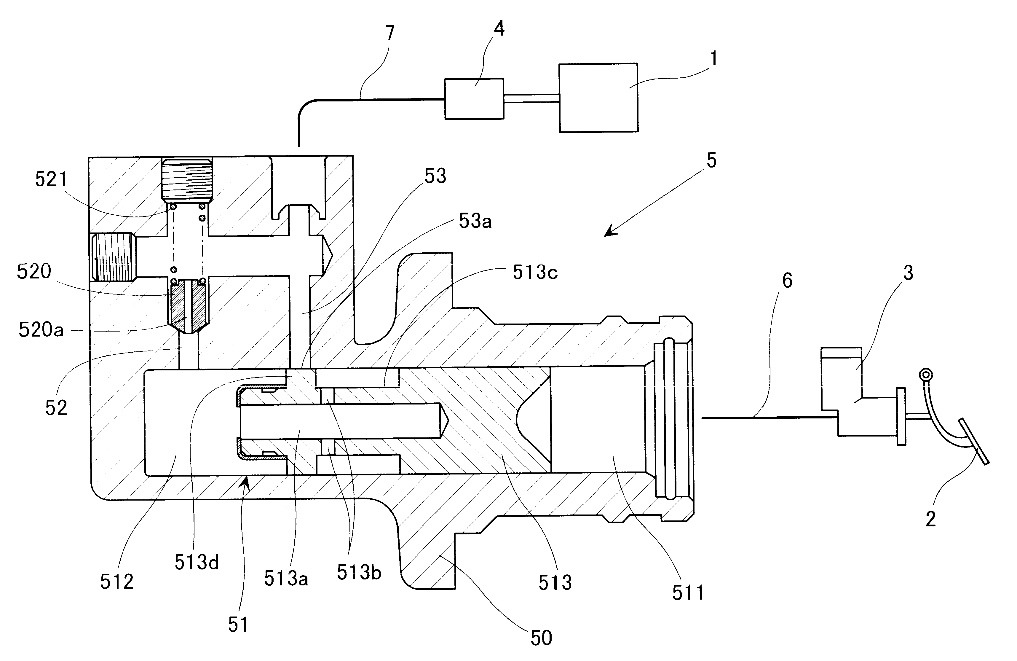
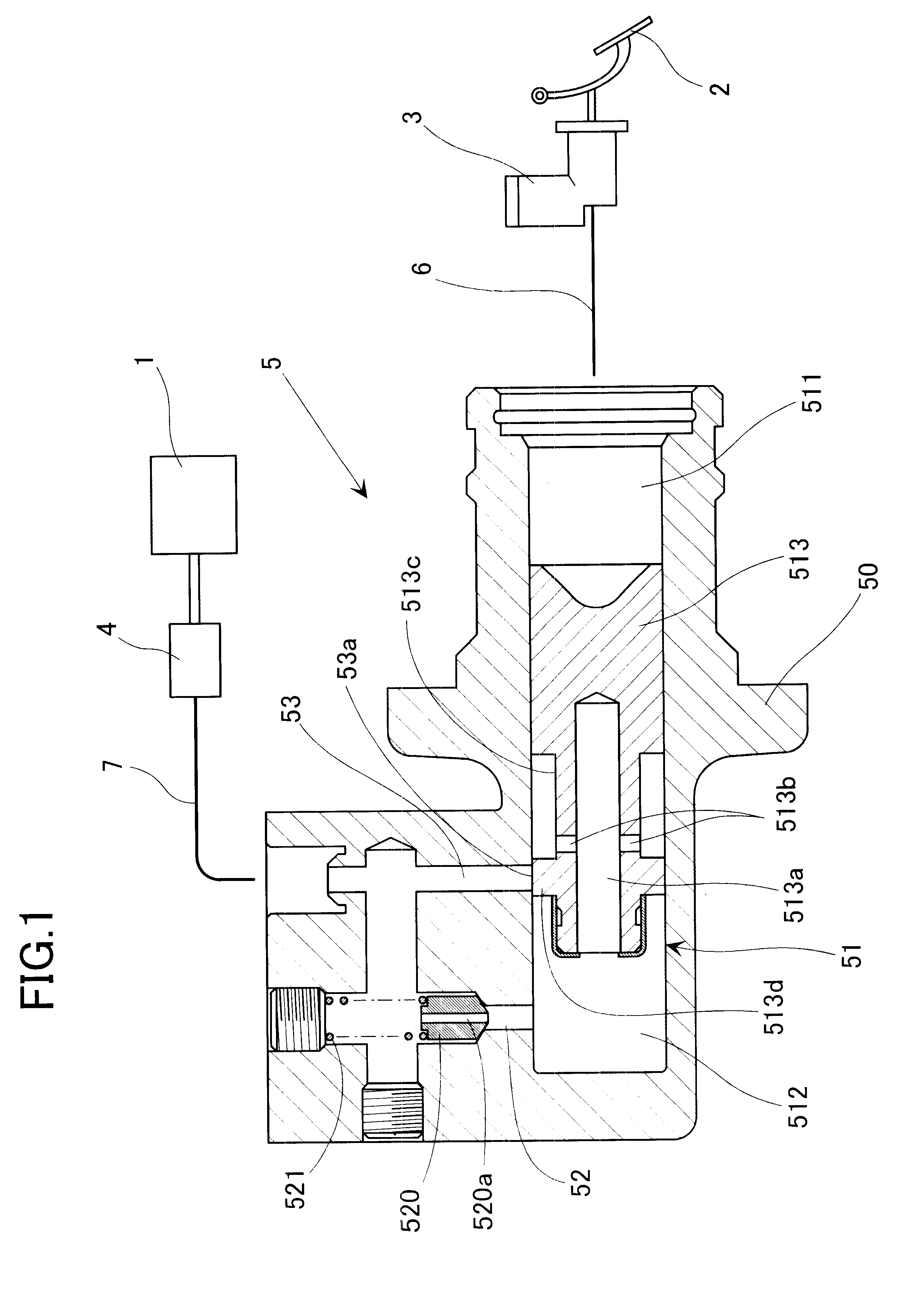
FIG. 1 shows an apparatus for hydraulically operating a clutch 1 which is assembled, or built, in a manual transmission for a motor vehicle. The apparatus switches the clutch 1 from an engaged state to a disengaged state by the operation of depressing a clutch pedal 2 which is defined as a clutch operating member. This apparatus for hydraulically operating the clutch 1 has a clutch master cylinder 3 which generates a hydraulic pressure depending on the degree of depression of the clutch pedal 2, and a clutch operating cylinder 4 which s witches the clutch 1 from the engaged state to the disengaged state as a result of transmission of the hydraulic pressure from the clutch master cylinder 3. Between the clutch master cylinder 3 and the clutch operating cylinder 4, there is interposed a flow limiting device (or a flow restricting device) 5. When a driver of the motor vehicle releases the depression of the clutch pedal 2 to thereby switch the clutch 1 from the disengaged state to the e...


PUM


Abstract

A flow limiting device provided between a clutch master cylinder and a clutch operating cylinder has a first fluid chamber on one axial side in communication with the clutch master cylinder, a second fluid chamber on the axially opposite side in communication with the clutch operating cylinder, and a piston for partitioning the first and second fluid chambers. The piston has on a circumference thereof an annular groove in communication with the second fluid chamber through an inner passage, and a land on the axially opposite side of the annular groove. As passages to communicate the second fluid chamber and the clutch operating cylinder, there are provided a first passage opening into the cylinder portion in a position away in the axially opposite side relative to the land when the piston is in one stroke position at which the clutch is disengaged, and a second passage opening into the cylinder portion at a position coinciding with a position of the annular groove when the piston is in said one stroke position. When the piston is in an axially intermediate stroke position in which the clutch is in the clutch-slipping state, an opening of the second passage is closed by the land. In the first passage, there is interposed a one-way valve having an orifice which has an easy flow direction in a direction toward the clutch operating cylinder.

Description

1. Field of the InventionThe present invention relates to an apparatus for hydraulically operating a clutch which is assembled or is contained in a manual transmission for a vehicle such as a motor vehicle, or the like.2. Description of Related ArtThis kind of conventional apparatus for hydraulically operating a clutch is provided with: a clutch master cylinder which generates a hydraulic pressure depending on the operation (i.e., the depression) of a clutch pedal which is defined as a clutch operating member; and a clutch operating cylinder which operates the clutch as a result of transmission of a hydraulic pressure from the clutch master cylinder. Further, Published Unexamined Japanese Patent Application No. 83518 / 1987 discloses an apparatus in which a flow limiting (or a flow restricting) device is interposed between the clutch master cylinder and the clutch operating cylinder. In this apparatus, in switching the clutch from a disengaged state to an engaged state, the flow amoun...

Claims


Application Information

Patent Timeline
Patent Type & Authority Patents(United States)
IPC IPC(8): F16D48/00F16D48/02F16D25/08
CPCF16D25/14F16D48/02F16D2048/0212F16D2048/0221
Inventor KAMIYA, TADASHIUDOU, HIDEOFUJIMOTO, SHINJI
Owner HONDA MOTOR CO LTD
Why Eureka
Try Eureka