Burr breaking device in high-frequency welded pipe and diagnosis method
A high-frequency welded pipe and welding device technology, applied in the field of high-frequency steel pipe manufacturing, can solve the problems of damaged tools, reduced steel pipe production work rate, time-consuming and labor-intensive, etc.
- Summary
- Abstract
- Description
- Claims
- Application Information
AI Technical Summary
Problems solved by technology
Method used
Image
Examples
Embodiment 1
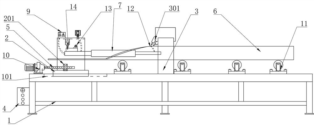
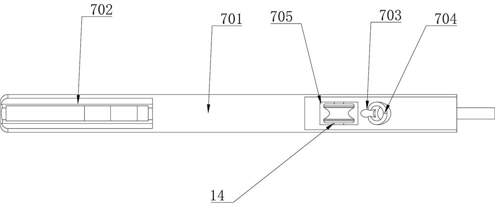
[0041] like Figure 1-6Among them, a device and a diagnosis method for breaking burrs in a high-frequency welded pipe, including a bracket 1, a sliding movable frame 2 is arranged on the bracket 1, a rotatable cutting mechanism 7 is arranged on the movable frame 2, and the cutting mechanism 7 is provided with A guide hole 704 and a guide wheel 8 are provided, one end of the cutting mechanism 7 is provided with an oil cylinder 706, one end of the oil cylinder 706 is provided with a cutter 707, and the bracket 1 is provided with a movable weldment 6;
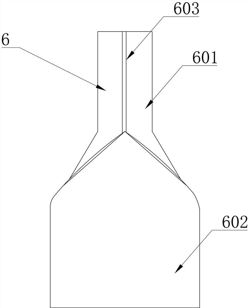
[0042] The welding piece 6 forms the burr 12 during the welding process to form the welded pipe 601 , and the cutting mechanism 7 is used for cutting the burr 12 . With this structure, the motor 10 is driven to move the moving frame 2 horizontally, so that the cutting mechanism 7 can extend into the weldment 6 to adjust the horizontal position of the guide hole 704 relative to the burr 12, and the oil pump 14 is driven to make the...
Embodiment 2
[0061] A diagnostic method for a burr breaking device in a high-frequency welded pipe, comprising the following steps: pre-welding preparation: driving the welding device 3 to weld part of the welded plate 602 into a welded pipe 601, so that burrs 12 are formed on the welded pipe 601; cutting Preparation of the position for coarse adjustment of the mechanism: drive the motor 10 to move the cutting rod 701 on the moving frame 2 in the horizontal direction, so that the cutting rod 701 extends into the welded pipe 601, so that the guide hole 704 is located under the burr 12, and the position of the cutting mechanism Adjustment: Press the lift button 403, the oil pump 14 works, so that one end of the cutting mechanism 7 is lowered, so that the other end of the cutting mechanism 7 is raised, and the motor 10 is driven several times again, and the horizontal position of the cutting mechanism 7 is adjusted so that the burr 12 passes through the guide. Puncture hole 704; interrupt data...
Embodiment 3
[0065] Further illustrate in conjunction with embodiment 1 and embodiment 2, as Figures 1~6, Manual monitoring should be done first when adjusting the type and changing lanes, set the switch knob 402 to the manual position on the operating table, start the oil pump 14, press the lift button 403, and transmit the signal to the PLC19, so that the PLC19 sends an instruction to control the solenoid valve 15. , the oil cylinder 706 pushes the tool 707 to the designated position, presses the interrupt button 404, and sends a command to the solenoid valve 15 through the PLC19 to hear the sound of the oil cylinder 706 driving the tool 707; and then set the switch knob 402 to the automatic position, in the function visualization display Set the burr interruption time as 2s on the interface of the control software 1701 displayed in 18, press the interruption button 404, send an instruction to the solenoid valve 15 through the PLC 19, and the oil pump 14 drives the tool 707 to move conti...
PUM
 Abstract
Description
Claims
Application Information
 - R&D
- Intellectual Property
- Life Sciences
- Materials
- Tech Scout
- Unparalleled Data Quality
- Higher Quality Content
- 60% Fewer Hallucinations
Browse by: Latest US Patents, China's latest patents, Technical Efficacy Thesaurus, Application Domain, Technology Topic, Popular Technical Reports.
© 2025 PatSnap. All rights reserved.Legal|Privacy policy|Modern Slavery Act Transparency Statement|Sitemap|About US| Contact US: help@patsnap.com


