Pipeline drilling machine for building engineering

A technology for construction engineering and drilling machines, applied in portable drilling machines, drilling/drilling equipment, metal processing machinery parts, etc., can solve the problem of reducing the drilling efficiency of pipeline installation, large volume of pipeline drilling machines, and pipeline drilling processing Inconvenience and other problems, to achieve the effect of improving drilling efficiency, small size, and increasing contact area

Inactive Publication Date: 2018-10-09
江西佰嘉实业有限公司
View PDF6 Cites 1 Cited by
  • Summary
  • Abstract
  • Description
  • Claims
  • Application Information

AI Technical Summary

Problems solved by technology

[0003] When the pipeline is installed and used, part of the pipeline needs to be drilled. The pipeline drilling machine in the prior art has a large volume and cannot be carried when used. The pipeline can only be processed in the workshop, thereby reducing the installation time of the pipeline. Drilling efficiency, and in the prior art, when the pipe is drilled outdoors with a hand-held electric drill, the pipe needs to be fixed manually, and the hole spacing needs to be manually measured and marked by the user, which makes the drilling process of the pipe very inconvenient

Method used


Image

  • Pipeline drilling machine for building engineering
  • Pipeline drilling machine for building engineering
  • Pipeline drilling machine for building engineering

Examples


Embodiment 1

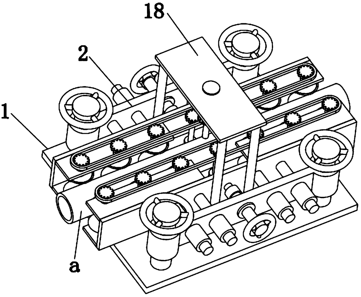
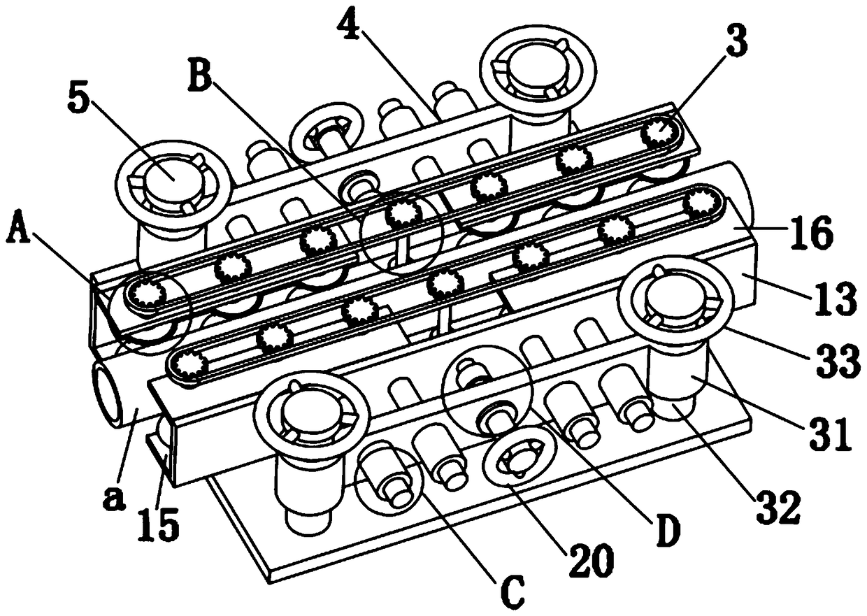
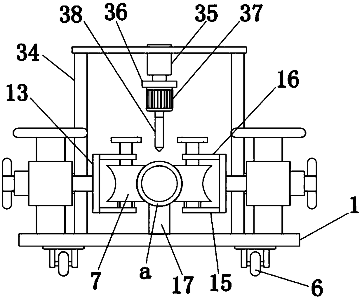
[0036] Embodiment one please refer to Figure 1-8, a pipeline drilling machine for construction engineering, comprising a support plate 1 and a fixing device 2, the top of the support plate 1 is fixed with a fixing device 2, and the fixing device 2 includes a progressive device 3, a lateral adjustment device 4 and a longitudinal Adjusting device 5, two advancing devices 3 are provided, and the two advancing devices 3 are symmetrically distributed above the support plate 1, and the two advancing devices 3 are located on both sides of the pipeline a, and the advancing devices 3 include driving Roller 7, gear chain 8, driven gear 9, driving gear 10, rotating shaft 11, progressive motor 12, fixed plate 13, connecting shaft 14, first connecting plate 15 and second connecting plate 16, described fixing plate 13- The bottom and the top of the side are respectively fixed with a first connecting plate 15 and a second connecting plate 16, the progressive motor 12 is fixed on the top of ...

Embodiment 2

[0037] Embodiment 2 Please refer to Figure 1-8 , the outer side of the driving roller 7 is an arc-shaped structure, and the outer side of the driving roller 7 is fixed with an anti-skid pad 19 . Such setting increases the contact area between the driving roller 7 and the pipeline, preventing slippage between the driving roller 7 and the pipeline.

Embodiment 3

[0038] Embodiment three please refer to Figure 1-8 , the horizontal adjustment device 4 includes a horizontal handle 20, a mounting plate 21, a horizontal screw rod 22, a buffer 23, a fixed shaft 24 and a support shaft 25, one end of the support shaft 25 is fixedly connected with the fixed plate 13, and the support The other end of the shaft 25 runs through the mounting plate 21, and the supporting shaft 25 is slidably connected with the mounting plate 21. The middle part of the mounting plate 21 is provided with a threaded hole, and the mounting plate 21 is movably connected with the horizontal screw rod 22 through the threaded hole. One end of the horizontal screw rod 22 is fixed to the horizontal handle 20, the other end of the horizontal screw rod 22 is fixed to the fixed shaft 24 through the buffer member 23, and the end of the fixed shaft 24 away from the buffer member 23 rotates through the bearing and the fixed plate 13 The two ends of the installation plate 21 are sy...


PUM


Abstract

The invention discloses a pipeline drilling machine for building engineering. The machine comprises a supporting plate, and a fixing device which is fixed to the top part of the supporting plate, wherein the fixing device comprises two progressing devices, a transverse adjusting device and a longitudinal adjusting device; the two progressing devices are symmetrically distributed to the upper partof the supporting plate, and each progressing device comprises a driving roller, a gear chain, a driven gear, a driving gear, a rotating shaft, a progressing motor, a fixing plate, a connecting shaft,a first connecting plate and a second connecting plate; the first connecting plates and the second connecting plates are correspondingly fixed to the bottom parts and the top parts of the sides of the fixing plates; the progressing motors are fixed to the top parts of the first connecting plates; a drilling device is fixed into the middle part of the top part of the supporting plate. The machineis small in size, and convenient to carry; pipelines with different diameter can be automatically drilled and processed; and the pipeline drilling efficiency is improved.

Description

technical field [0001] The invention relates to the technical field of pipeline drilling, in particular to a pipeline drilling machine for construction engineering. Background technique [0002] Drilling refers to the operation of machining a hole in a solid material with a drill bit; a drilling machine refers to the use of a tool that is harder and sharper than the target object through rotary cutting or rotary extrusion, leaving a cylindrical shape on the target object. The machinery and equipment for holes or holes are collectively referred to as drilling rigs, punching machines, drilling machines, through-hole machines, etc., by drilling precision parts to achieve the desired effect. Drilling machines include semi-automatic drilling machines and full-automatic drilling machines. Automatic drilling machine. [0003] When the pipeline is installed and used, part of the pipeline needs to be drilled. The pipeline drilling machine in the prior art has a large volume and cann...

Claims


Application Information

Patent Timeline
Patent Type & Authority Applications(China)
IPC IPC(8): B23B45/02B23Q3/06
CPCB23B45/02B23Q3/062
Inventor 不公告发明人
Owner 江西佰嘉实业有限公司
Why Eureka
Try Eureka