Locking device for use with stackable shipping containers

a technology for stackable shipping containers and locking devices, which is applied in the direction of snap fasteners, couplings, manufacturing tools, etc., can solve the problems of not providing a combined spring-biased twist-head and hook lock, and achieve the effect of increasing the flexibility of the operator

Inactive Publication Date: 2002-10-08
BUFFERS USA
View PDF7 Cites 19 Cited by
  • Summary
  • Abstract
  • Description
  • Claims
  • Application Information

AI Technical Summary

Benefits of technology

The primary object of the locking device according to the invention is directed to increasing an operator's flexibility for respectively engaging or removing a lock during the stacking or unstacking of containers on which the lock is used.
When the lock has been left engaged in the lower container after unloading of the top container, the spring-biased lock can be removed from the lower container by manually lifting the lock up from the engaged corner casting the height of its lower shear block and turning it 90.degree. in the corner casting to align the horizontal length of the hook with the longitudinal direction of the ISO aperture. This permits the lock to be further lifted up and completely disengaged from the corner casting without the need to compress the spring biased hook.
This flexibility allows operators at a loading terminal to do all lock engagement and removal on the carrier (stacked operation) and operators at an unloading terminal to do lock disengagement on the ground (wheeled operation) or vice versa.
This operational flexibility is achieved regardless of the original position in which the lock was fitted to the container enabling the operator at an unloading terminal to decide how to remove the lock instead of being required to pursue conventional practice. The invention also gives the operator an indicator showing the open or closed position of the hook that is clearly visible from the ground and from the platform at the end of the carrier. This is possible due to the extended compression pad that covers the container corner castings out past the side of the container. This extended load pad makes it also possible to direct the load force from the top container straight down into the stacking posts of the bottom container, thereby reducing the bending forces occurring with existing locks that have a compression load pad limited to surrounding the aperture hole of the engaged corner casting.
The lock according to the invention also gives the operator an alternative disengagement method in case the automatic lock malfunctions and does not open when the container is lifted. By pulling the handle operating the twist-head from the ground on the side of the carrier, the twist-head is turned to open, thus allowing the container to be unloaded in spite the malfunctioning hook side of the lock.

Problems solved by technology

However, none of these provide a combined spring-biased twist-head and hook lock engaged between the stacked containers with a compression pad extending past the edges of the stacked containers to house means for operating the twist-head and an indicator to alert the operator whether the spring-biased hook is an open or closed position.

Method used


Image

  • Locking device for use with stackable shipping containers
  • Locking device for use with stackable shipping containers
  • Locking device for use with stackable shipping containers

Examples


Embodiment Construction

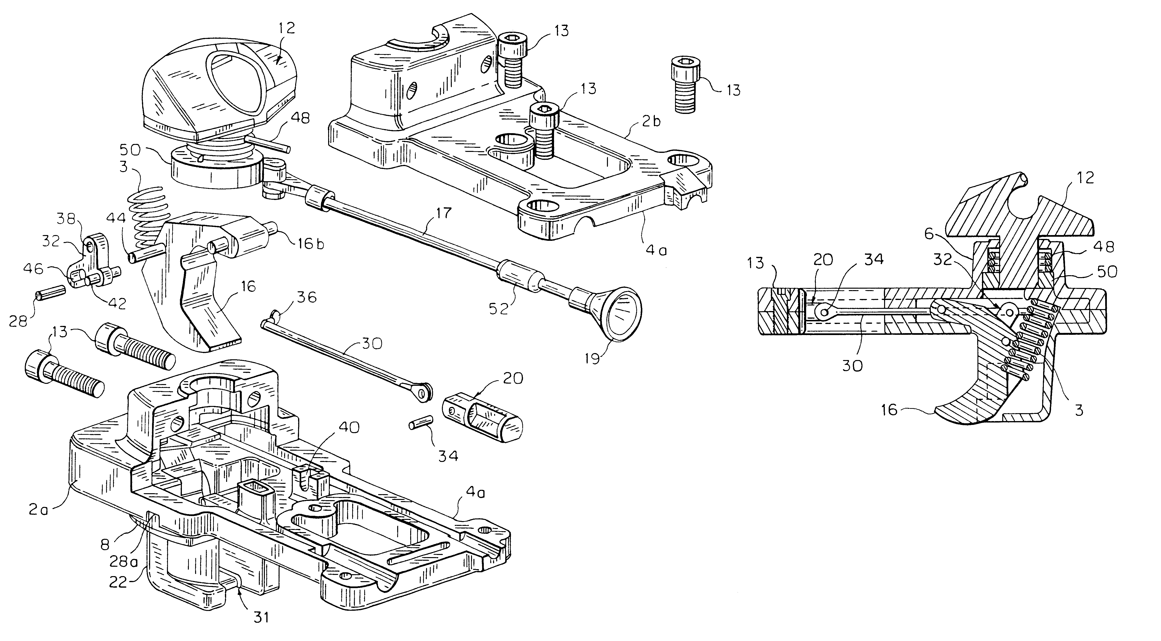
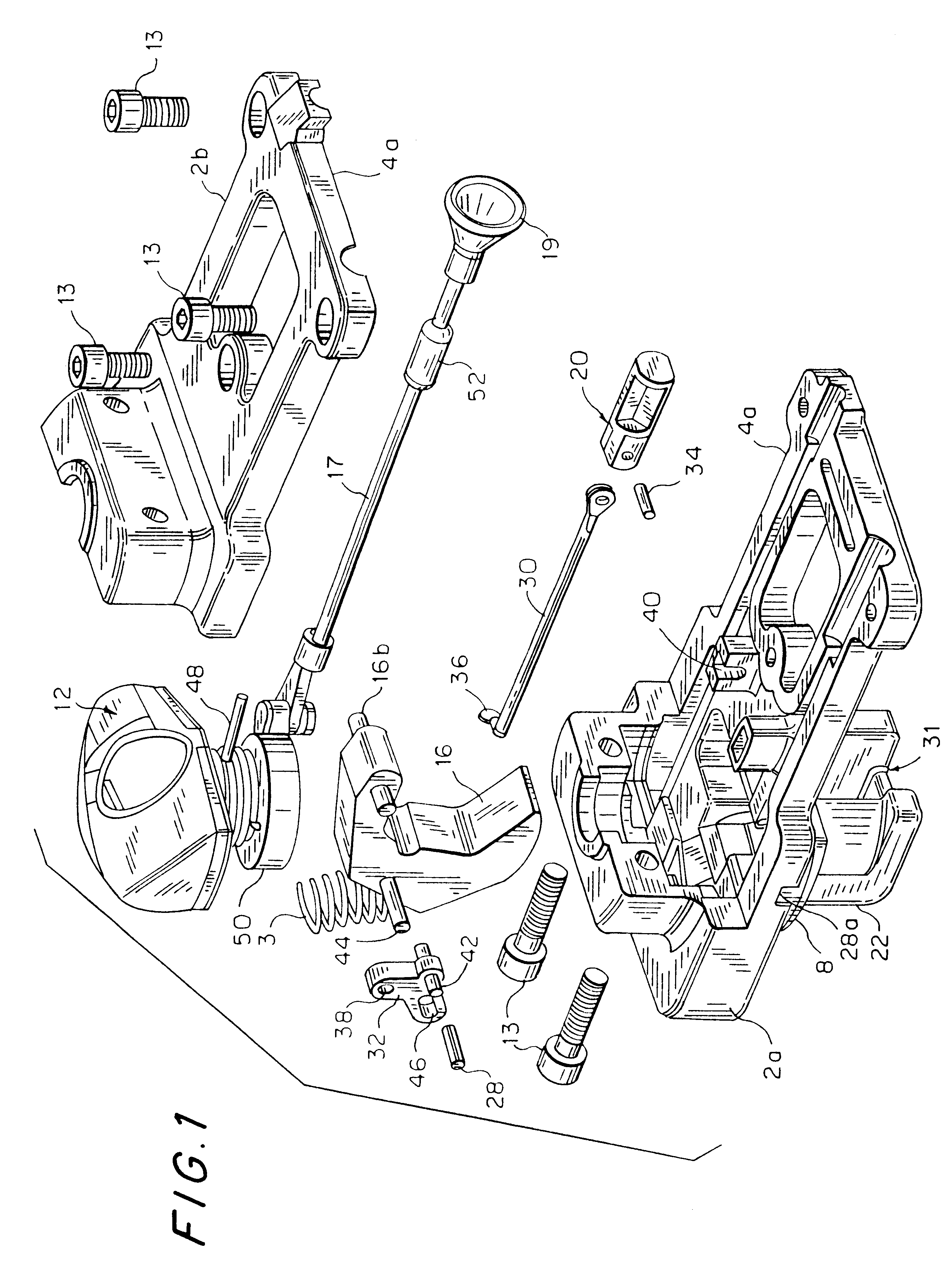
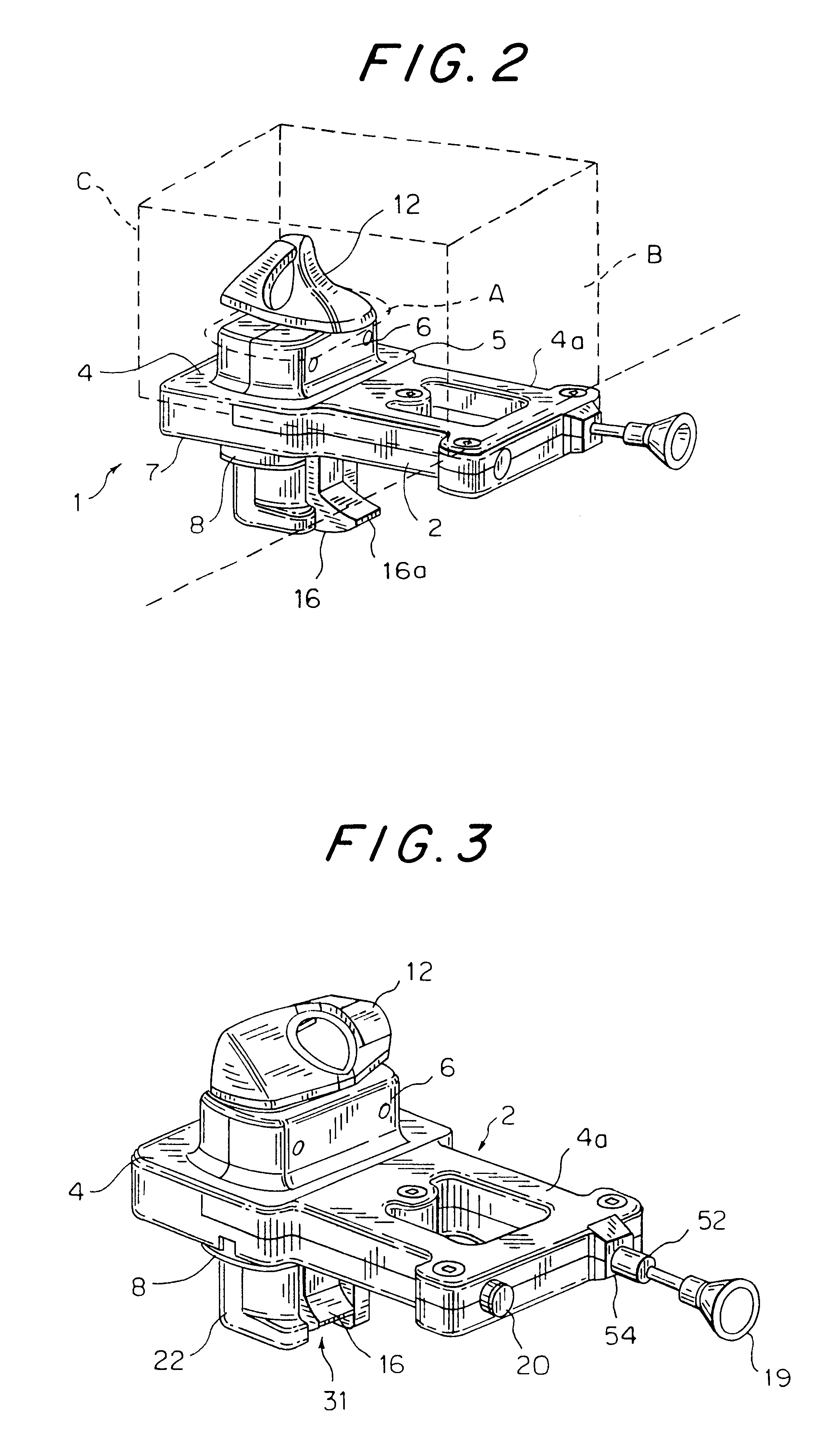
As shown in FIG. 2, locking device 1 comprises a housing 2 when housing sections 2a and 2b, shown in FIG. 1, are joined together by bolts 13. Housing 2 is provided with a compression pad 4 on which upper and lower shear blocks 6, 8 are integrally formed. Both upper and lower shear blocks 6, 8 have a longitudinal length 14, best shown in FIG. 6, which corresponds to the longitudinal length of a standard ISO corner casting aperture A of a corner castings B of container C which can be stacked on carriers including rail cars. For purposes of clarity only upper container C with casting B having aperture A are shown in phantom lines on FIG. 2, it being understood that a top casting on a lower container casting B has an identical size aperture engaged around shear block 8 when the top container C is stacked with the lock on the lower container. When locking device 1 is engaged between the corner castings on an upper and lower container in a stack to limit their relative movement, the conta...


PUM


Abstract

The invention is directed to a locking device which can be engaged in a conventional ISO aperture of a corner casting of an upper and lower shipping container stacked on a carrier to lock the containers together. The locking device has a housing having a compression pad with an upper and lower shear block. A spring-biased twist-head is engaged to the upper shear lock, and a spring-biased hook is engaged in the housing. When the upper and lower shear block of the lock are respectively engaged in the ISO aperture of the upper and lower corner castings of the stacked containers and the twist-lock and the hook are each in a closed position within the corner casting, relative movement between the containers is limited.

Description

1. Technical Field of the InventionThe invention is directed to a locking device for engagement between stackable shipping containers to lock the containers together, wherein the locking device is engaged in an upper and lower conventional ISO aperture of corner castings on the containers to arrest their relative movement.2. Prior ArtAutomatic container locks have been in use with stackable shipping containers for over 20 years. Both hook locks and twist-head locks that have been each separately welded down on a flatcar to engage a single container have been used during this period. Automatic locks have also been designed to work between vertically stacked containers. However, none of these provide a combined spring-biased twist-head and hook lock engaged between the stacked containers with a compression pad extending past the edges of the stacked containers to house means for operating the twist-head and an indicator to alert the operator whether the spring-biased hook is an open o...

Claims


Application Information

Patent Timeline
Patent Type & Authority Patents(United States)
IPC IPC(8): B65D90/00
CPCB65D90/0013Y10T403/599Y10T24/44Y10T24/28
Inventor HOVE, JOHN
Owner BUFFERS USA
Why Eureka
Try Eureka