Multi-stage self-cleaning control for oven

Inactive Publication Date: 2002-10-08
BSH HOME APPLIANCES CORP
View PDF10 Cites 41 Cited by
  • Summary
  • Abstract
  • Description
  • Claims
  • Application Information

AI Technical Summary

Problems solved by technology

Although recent improvements of cooking devices have employed multiple cooking energy sources such as microwave generators, convection heating sources, and conventional radiant heating elements, the control of pyrolytic cleaning cycles is limited to actuation of radiant heating elements which can be powered to achieve the high temperatures in the oven that are required for pyrolytic cleaning.

Method used


Image

  • Multi-stage self-cleaning control for oven
  • Multi-stage self-cleaning control for oven
  • Multi-stage self-cleaning control for oven

Examples


Embodiment Construction

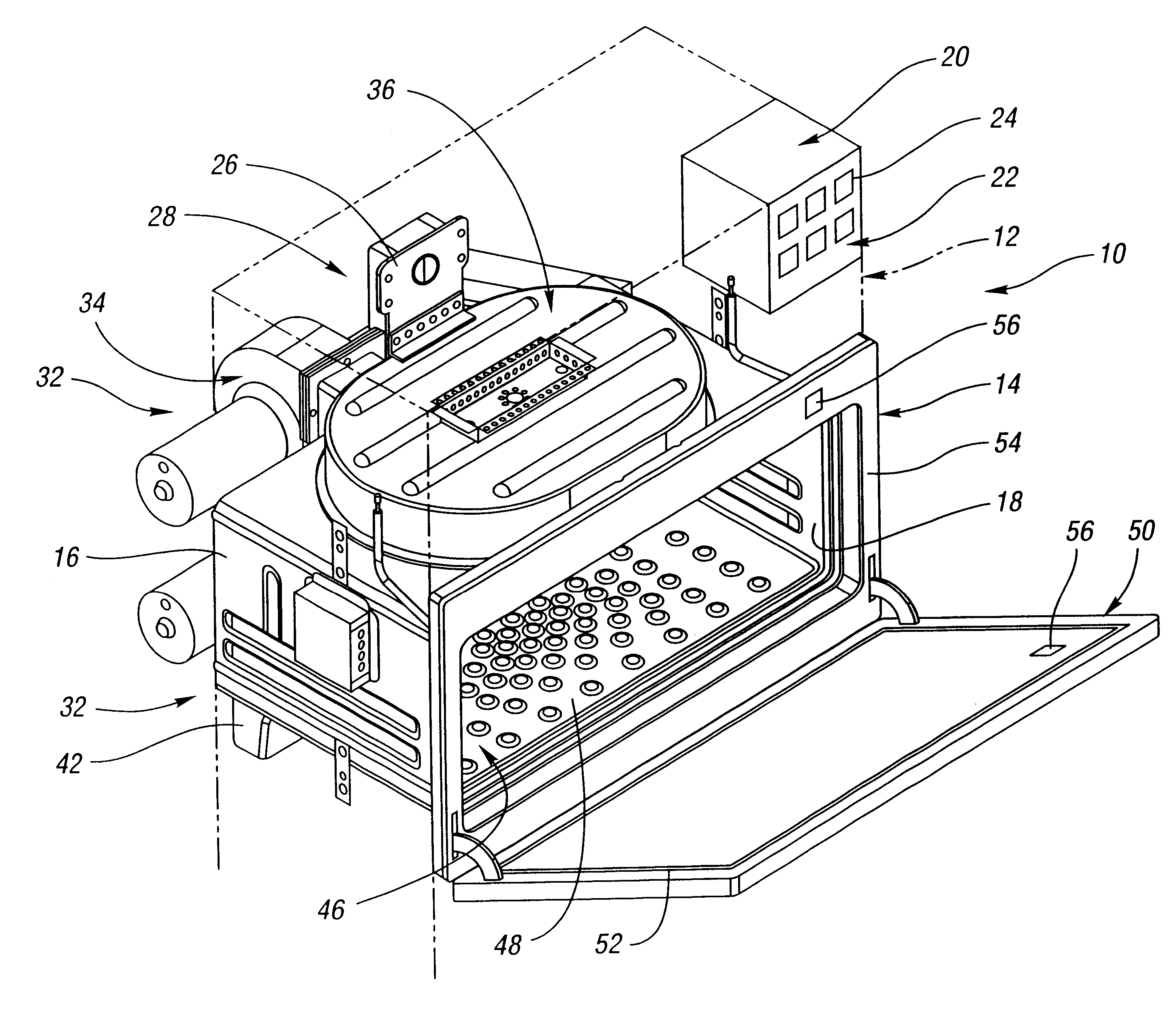
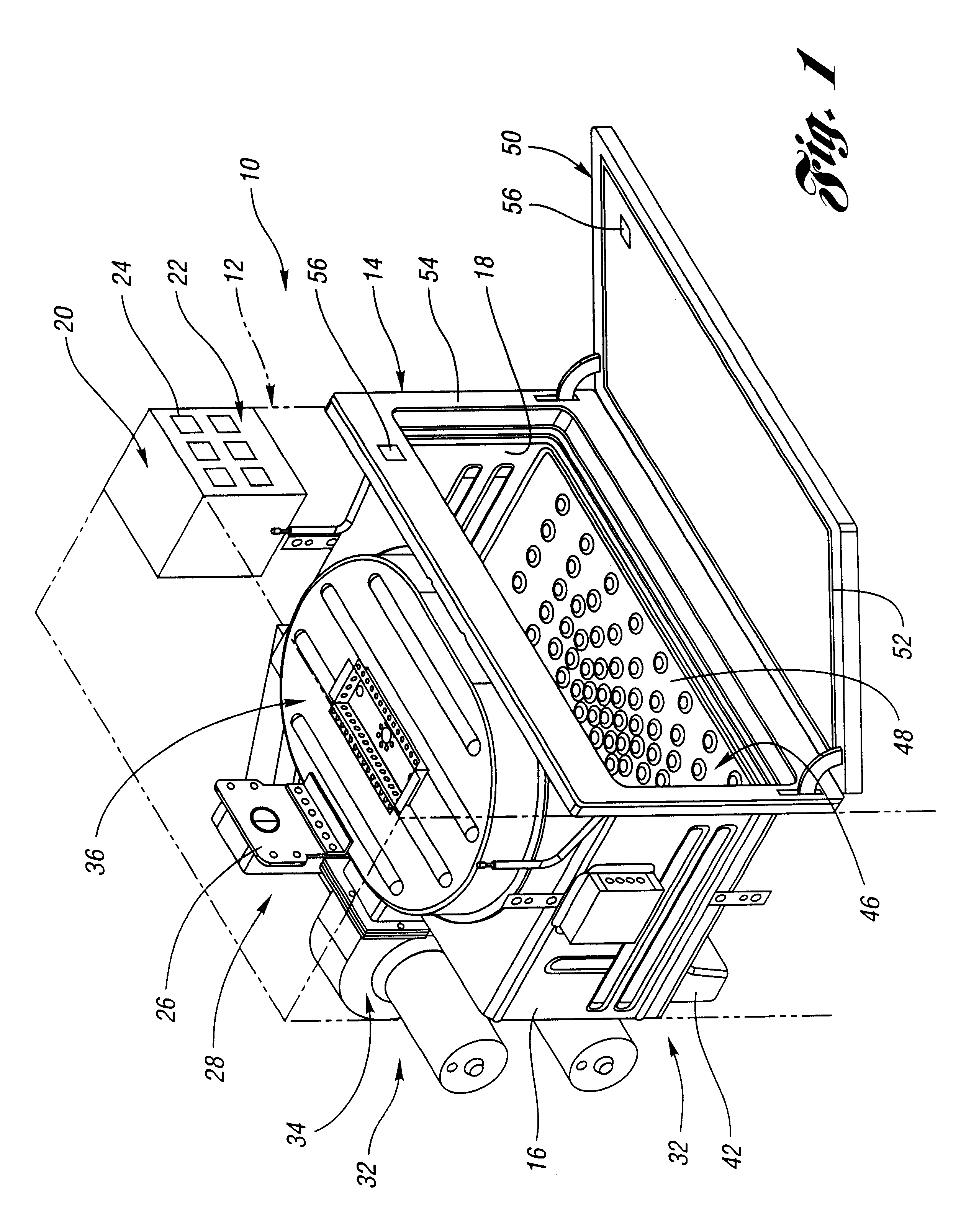
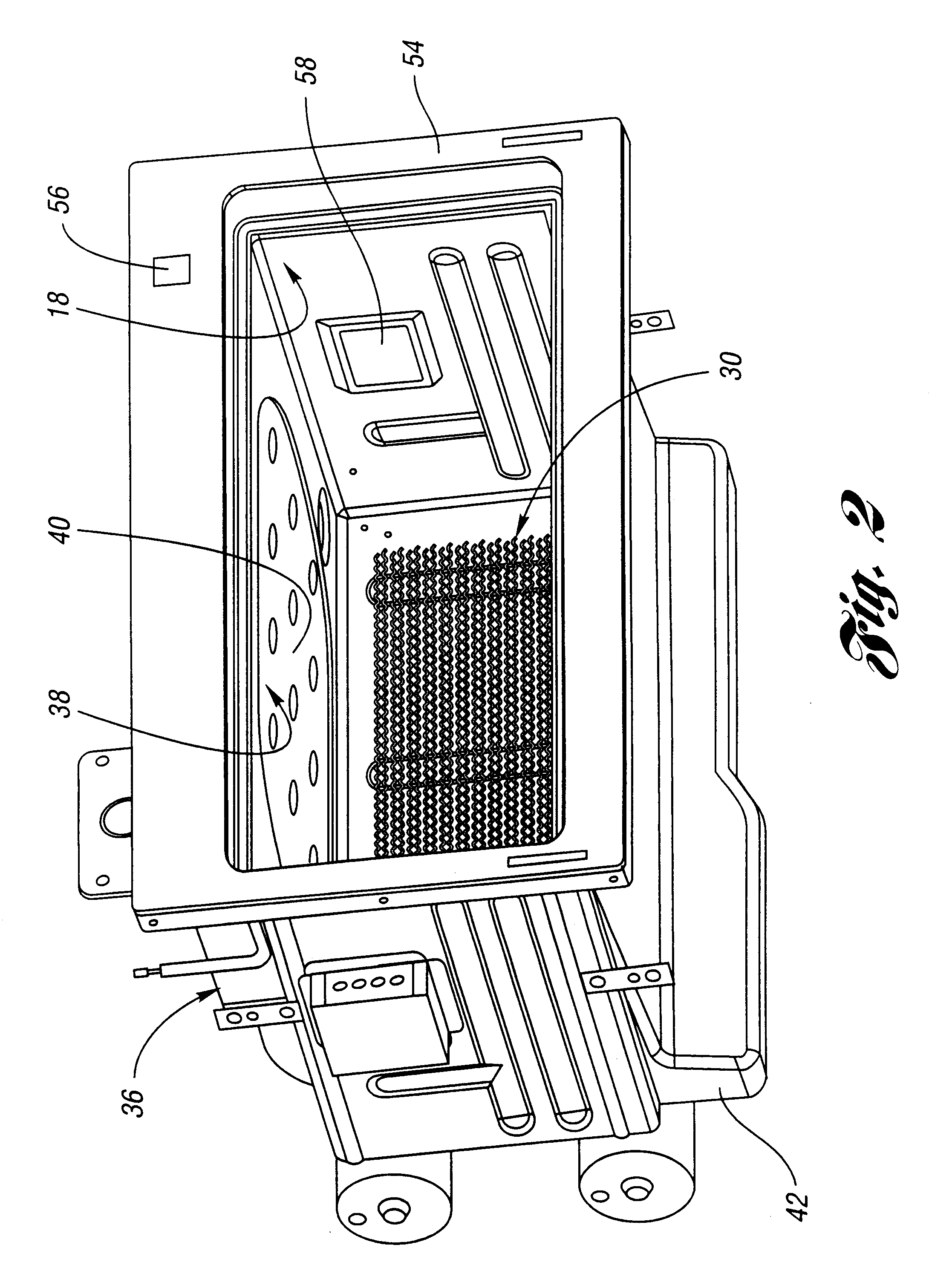
The present invention overcomes the above mentioned disadvantages by providing a combination cooking source oven having a control that generates a multiple stage pyrolytic cleaning operation. The present invention provides a method and apparatus for pyrolytically cleaning an oven chamber by sealing the chamber, raising the temperature to a pyrolytic cleaning level for a first operating period in which the blower operation is disabled, maintaining the temperature of the pyrolytic cleaning level and actuating the blower operation in a second time period following the first operating period.

In the preferred embodiment, a blower of a jet impingement cooking source is disabled while up to four heating elements are operated to obtain a pyrolytic cleaning temperature within a sealed oven chamber. An additional stage is initiated by the oven control to generate jet impingement currents throughout the oven chamber and the passageways in communication with the chamber that may have been soile...


PUM


Abstract

A method and a cooking appliance has a pyrolytic cleaning control in which multiple stages permit volatile residue to be incinerated before inducing air current flow that can complete the cleaning process throughout the oven housing. The oven combines cooking energy sources, including convection current heating and preferably, jet impingement heating, whose blowers are disabled during a first stage of pyrolytic cleaning to avoid uncontrolled ignitions within the appliance. The second stage of the pyrolytic cleaning process induces current flow to distribute pyrolytically heated air throughout the housing and complete the cleaning process in the apparatus.

Description

1. Field of the InventionThe present invention relates to a method and apparatus for controlling pyrolytic cleaning in a combination microwave and convection heating oven in which blower actuation, such as jet impingement actuation, is deferred to a time or an event near the terminal portion of the cleaning cycle.2. Background ArtMany cooking ovens have a pyrolytic cleaning function in which the heating elements are operated to obtain a pyrolytic cleaning temperature, for example 800.degree. F. (427.degree. C.) within the oven chamber. Typically, the oven is sealed so that accumulated debris on the walls of the oven can be incinerated and removed as ash residue after the pyrolytic cleaning cycle has terminated. The operation of such cleaning cycles is regulated and test results must comply with standards established, for example Underwriters Laboratory (UL) 858 standard for household electric ranges.Although recent improvements of cooking devices have employed multiple cooking energ...

Claims


Application Information

Patent Timeline
IPC IPC(8): H05B6/80
CPCH05B6/6405H05B6/6473
Inventor UY, DINDO S.WALSH, CYRAL MARTIN
Owner BSH HOME APPLIANCES CORP
Why Eureka
Try Eureka