Stable artificial neutral point in a three phase network of single phase rectifiers

Inactive Publication Date: 2002-10-15
VERTIV ENERGY SYST INC
View PDF8 Cites 24 Cited by
  • Summary
  • Abstract
  • Description
  • Claims
  • Application Information

AI Technical Summary

Benefits of technology

Other advantages include the possibility to change from a 3.times.400V network to a 3.times.2

Problems solved by technology

If there is no available neutral point in the three phase network, the neutral

Method used


Image

  • Stable artificial neutral point in a three phase network of single phase rectifiers
  • Stable artificial neutral point in a three phase network of single phase rectifiers
  • Stable artificial neutral point in a three phase network of single phase rectifiers

Examples


Embodiment Construction

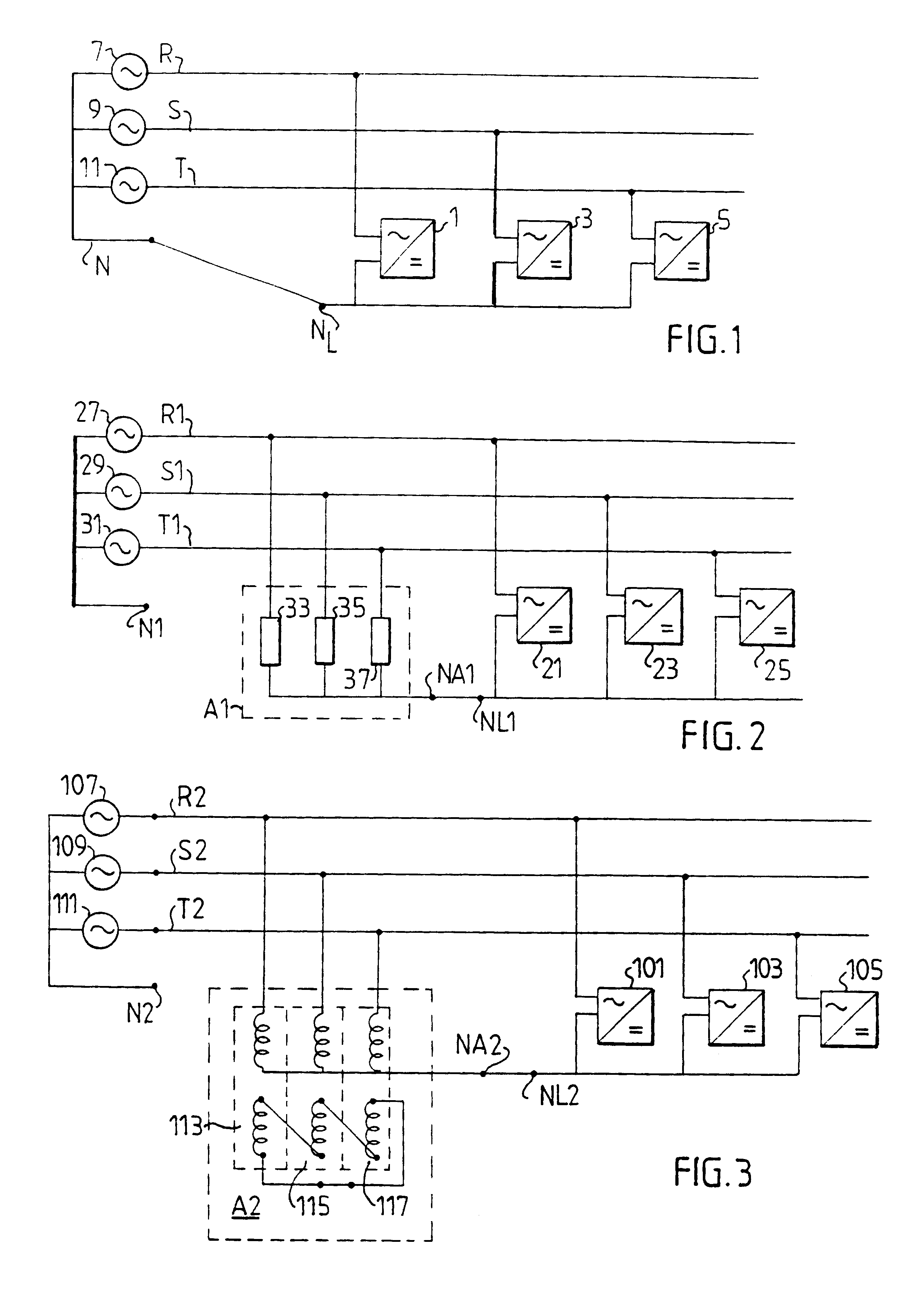
FIG. 1 shows a prior art three phase rectifier based on single phase rectifiers. The first primary terminal of three single phase rectifiers 1, 3, 5 are connected to the three phases R, S, T of a three phase network. The second primary terminals are interconnected, that is, the rectifiers are connected in a star configuration. The neutral conductor N must be connected, as shown in the Figure.

The phase voltage of each phase is indicated schematically by a voltage generator, 7, 9, 11, respectively.

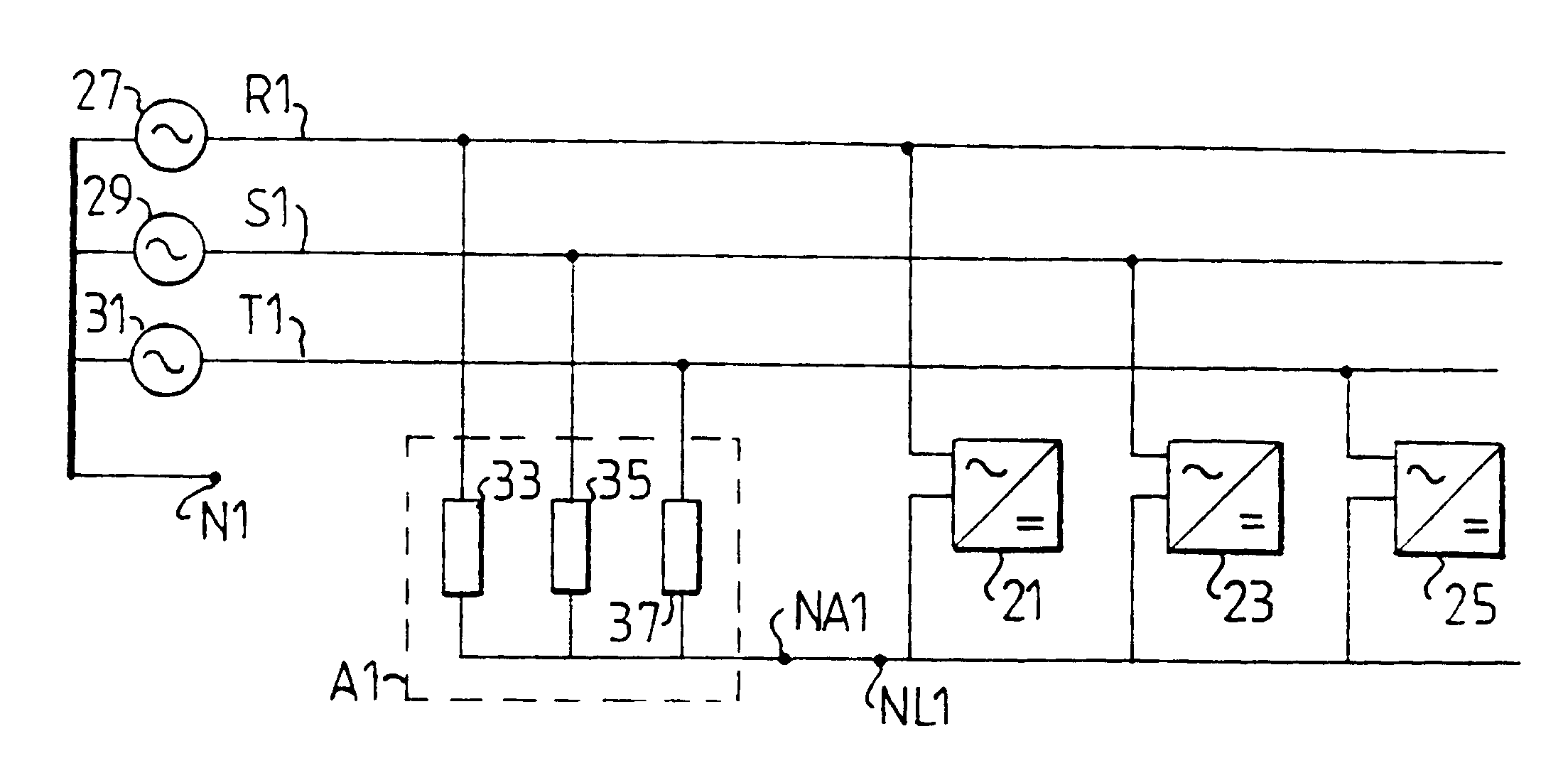
FIG. 2 shows a three phase rectifier similar to the one shown in FIG. 1. The first primary terminal of three single phase rectifiers 21, 23, 25 are connected to the three phases R1, S1, T1 of a three phase network. The secondary terminal are interconnected to form an artificial neutral point NL1. The neutral conductor N1 of the network is not connected. The phase voltages are represented by a voltage generator, 27, 29, 31, respectively, for each phase. An artificial neutral point creation (A...


PUM


Abstract

An electric supply system comprising two or more phases (R2, S2, T2), one rectifier (101, 103, 105) for each phase, the second primary terminals of said rectifiers (101, 103, 105) being interconnected, also comprises an Artificial Neutral Point (ANP) creating means (A2) for creating an artificial neutral point (NA2) in the electric supply system, connected in parallel with said rectifiers. The ANP means (A2) short-circuits the zero sequence voltage component of the system but does not affect the positive and negative sequence components. The ANP means (A2) includes magnetic components of such a kind that the vector sum of the phase voltages is zero. According to a first embodiment, the ANP means (A2) comprises one transformer (113, 115, 117) for each phase, the primary winding of each transformer connected to the respective phase (R2, S2, T2) in a star configuration, the secondary windings serially connected and the interconnection point of the primary windings forming an artificial neutral point.

Description

1. Technical FieldThe present invention relates to a multiple-phase rectifying apparatus for use in an electric supply system comprising two or more phases, said apparatus comprising a single phase rectifier having a first and a second primary terminal, for each phase, each rectifier connected by its first primary terminal to the respective phase, the second primary terminals of said rectifiers being interconnected.2. Description of Related ArtSuch networks, and such rectifiers are generally known in the art of electric supply systems.OBJECT OF THE INVENTIONA rectifier for a three phase network may be designed using three single phase rectifiers connected in a star configuration. For example, for a 3.times.400V network, three 230V rectifiers may be used.If there is no available neutral point in the three phase network, the neutral point created by the three rectifiers in a star configuration may be unstable. Asymmetric effects between the phases may occur both in the stationary and ...

Claims


Application Information

Patent Timeline
IPC IPC(8): H02J3/26H02M7/217H02M7/06
CPCH02J3/26H02M7/217Y02E40/50
Inventor KARLSSON, MATSWOLPERT, TADEUS
Owner VERTIV ENERGY SYST INC
Why Eureka
Try Eureka