Conveyor and waste toner reservoir for an image-forming apparatus

Inactive Publication Date: 2002-10-15
LEXMARK INT INC
View PDF21 Cites 16 Cited by
  • Summary
  • Abstract
  • Description
  • Claims
  • Application Information

AI Technical Summary

Benefits of technology

A pumping cylinder may be mounted around the auger adjacent to the waste toner reservoir to further assist in pumping the toner. The pumping cylinder extends around helical blade of the auger such that as the auger rotates, the toner is forced through the pumping cylinder and into the waste toner reservoir. The pumping cylinder assists in preventing the toner from back-flowing from the waste toner reservoir into the areas of the drum. Preferably, the auger extends through the pumping cylinder and into the interior section of the waste toner reservoir to further assist in toner pumping.

Problems solved by technology

Therefore, there is a tradeoff between a large waste toner reservoir that can hold a large amount of residual toner without becoming filled and a smaller reservoir that fits within the image forming device without occupying an excessive amount of space.
These fans add cost to the printer, and a single image forming device often requires more than one fan to adequately move the toner.
The fans may also be unreliable, either failing to operate effectively or breaking-down requiring continual maintenance.
Breakdowns are especially likely because the fans are constantly exposed to the dry, powdery toner that may clog and foul the fan components.
A blocked toner removal system requires the printer to be taken off line and disassembled, which is time consuming and aggravating for a user.
Fans additionally add noise to the image-forming process which is undesirable because the devices are often positioned at user's workstations where a quiet atmosphere is maintained for efficient working conditions.
These gravity systems reduce the effective design alternatives for the apparatus because the positioning of the reservoir relative to the drum is critical.
Positioning the reservoir below the drum to utilize the gravity flow often requires an additional amount of space, thereby resulting in an increased overall size of the image forming apparatus.
This problem is compounded in color printing devices that have multiple drums and reservoirs.

Method used


Image

  • Conveyor and waste toner reservoir for an image-forming apparatus
  • Conveyor and waste toner reservoir for an image-forming apparatus
  • Conveyor and waste toner reservoir for an image-forming apparatus

Examples


Embodiment Construction

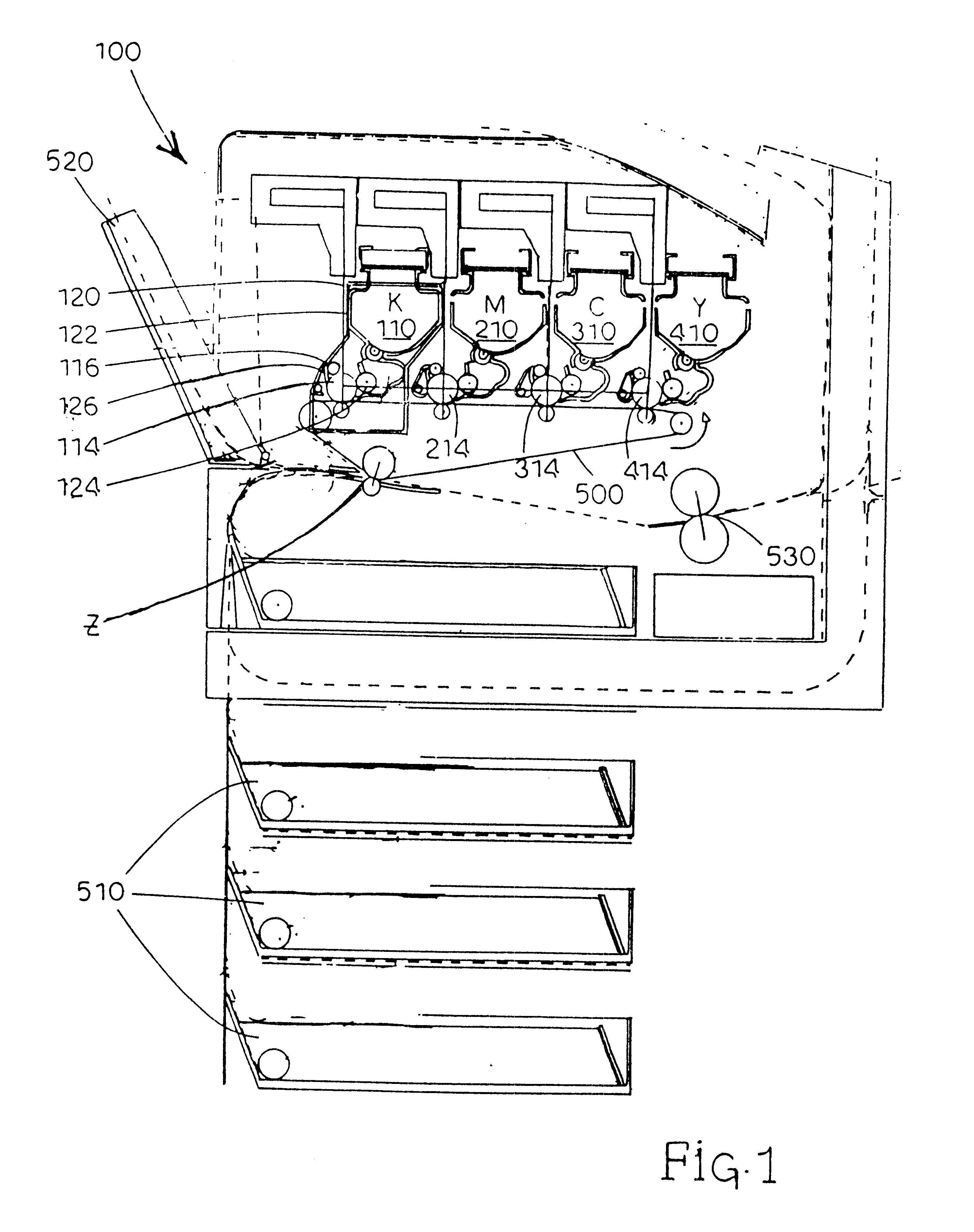
FIG. 1 illustrates the basic elements of an image forming apparatus and is incorporated for an understanding of the overall electrophotographic image forming process. A four cartridge color laser printer is illustrated as 100, however one skilled in the art will understand that the present invention is applicable to other types of image forming devices using toner for printing through a photoconductive drum. The image forming apparatus, generally designated 100, includes a plurality of similar toner cartridges 110, 210, 310, and 410. Each toner cartridge is of a similar construction but is distinguished by the toner color contained therein. In one embodiment, the device includes a black (K) cartridge 110, a magenta (M) cartridge 210, a cyan (C) cartridge 310, and a yellow (Y) cartridge 410. Each different color toner forms an individual image of a single color that is combined in layered fashion to create the final multi-colored image. The order of the cartridges may vary and is not...


PUM


Abstract

A waste toner removal device for transporting toner from a photoconductive drum within an image-forming apparatus. The invention includes a waste toner reservoir having outer walls forming an interior chamber for housing toner removed from the photoconductive drum. An opening is positioned within the outer walls into the interior chamber forming an upper chamber section extending above the opening and a lower chamber section extending below the opening. An auger extends along the photoconductive drum and unobstructed into the opening of the waste toner reservoir. The auger includes helical blades extending outward for moving the toner from the photoconductive drum into the waste toner reservoir. A pumping cylinder having a generally cylindrical shape extends around the auger adjacent to the waste toner reservoir. The diameter of the pumping cylinder is approximately equal to the helical blades wherein rotation of the auger creates a pumping action for moving toner into the said upper and lower chamber sections.

Description

BACKGROUND OF THE INVENTION1. Field of the InventionThe present invention relates generally to an image-forming apparatus and, more particularly, to an auger and waste toner reservoir for removing and storing residual toner from a photoconductive drum.2. Description of the Prior ArtImage forming devices including copiers, laser printers, facsimile machines, and the like, include a photoconductive drum (hereinafter referred to as a drum) having a rigid cylindrical surface that is coated along a defined length of its outer surface. The surface of the drum is charged to a uniform electrical potential and then selectively exposed to light in a pattern corresponding to an original image. Those areas of the photoconductive surface exposed to light are discharged thus forming a latent electrostatic image on the photoconductive surface. A developer material, such as toner, having an electrical charge such that the toner is attracted to the photoconductive surface is brought into contact wit...

Claims


Application Information

Patent Timeline
IPC IPC(8): G03G21/10
CPCG03G21/105
Inventor CAMPBELL, ALAN STIRLINGHORRALL, PAUL DOUGLASMOLLOY, JAMES JOHNPALUMBO, FRANKLIN JOSEPH
Owner LEXMARK INT INC
Why Eureka
Try Eureka