Joined web business form construction having removable elements

Inactive Publication Date: 2005-03-17
WARDKRAFT
View PDF16 Cites 5 Cited by
  • Summary
  • Abstract
  • Description
  • Claims
  • Application Information

AI Technical Summary

Benefits of technology

[0022] In one exemplary embodiment of the present invention, a business form construction, is described and includes a first generally planar substrate composed of a first material. The first substrate has first and second ends and first and second sides. A second generally planar substrate is also provided and is composed of a second material, that is distinct from the first material and has first and second sides and first and second ends. The second substrate has at least one die cut defining at least a first removable element. A material for securing the first and second substrates to one another along one of the first and second sides or first and second ends of each of the substrates is provided so that the substrates are connected in an adjacent and not overlapping configuration. Finally, a coating is applied over the material to prevent toner from substantially affixing to the material during imaging and to eliminate the occurrence of tracking or peppering.

Problems solved by technology

However, while effective in delivering the card to the end user, the process of assembling the mailing could be cumbersome in that it required the carrier to be printed and then to subsequently cut notches in the carrier to create areas to hold the corners of the card and then, finally placing of the card in the carrier.
In addition to being a somewhat cumbersome manufacturing process, the process itself can be expensive, in that it requires a number of pieces, a supply of cards, carriers and envelopes.
However, this construction, while eliminating some of the drawbacks associated with the above mentioned arrangement of putting a card into a carrier assembly, still suffered from unforeseen difficulties and created new problems in that the card was placed on the surface of the sheet of paper which then created a raised area which was disproportionate to the surrounding area.
Such a situation or arrangement often resulted in jamming of the printer or feeding apparatus when attempting to image or process the paper substrate with the card attached.
Unfortunately, while this particular construction resulted in manufacturing efficiencies it created difficulties for the end users as such product configurations had to be carefully or even gingerly fed through the printer, again slowing distribution to the end user and resulting in significant frustration of the end user or printer of the form construction.
Once again the manufacturer, while solving the problem of having the card extend above the surface of the sheet, faced the problem of alignment and having to carefully position the card within the receiving area.
In addition to problems associated with alignment, the manufacturer also faced the problem of also having to hold and secure the card in the receiving area.
While effective in over coming the problem with the card being placed on top of the substrate, such a construction then suffered from additional problems.
This limited the amount of cards that could then be placed in the tray to be fed to the printer or processing equipment.
This eliminated the need to apply a patch to hold the card in the area of a cut out into which a card would be inserted; however, this construction still suffers from other drawbacks.
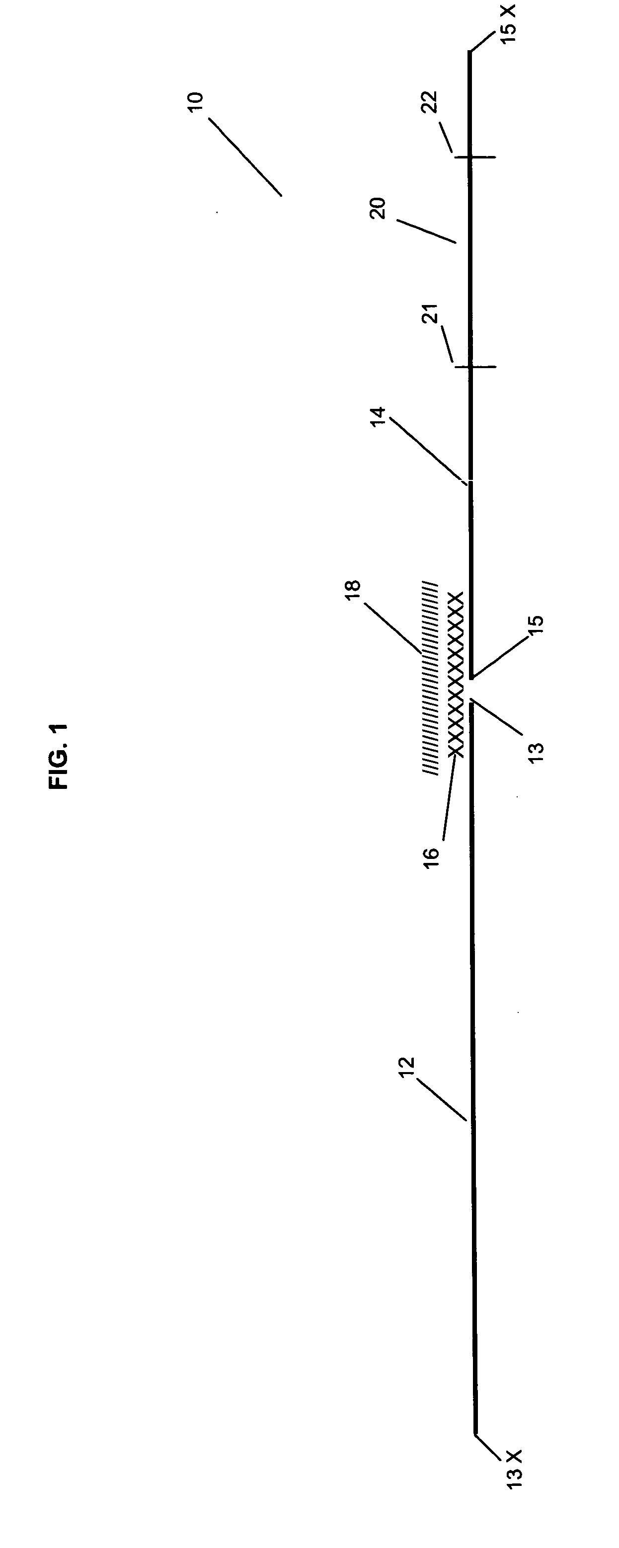
As such, the top surface of the card would still be above the top surface of the paper substrate leading to an arrangement that still suffered from difficulties in processing the card due to the differential thickness arising out of the card sticking out of the well or recessed area.
However, such cards are generally undesirable in that they are subject to being easily torn or destroyed and thus have only limited use or application.
However, such constructions while attractive from a manufacturing perspective also did not completely solve the processing of the form construction.
As expected however, this arrangement creates a bump in the form and contributes again to processing difficulties in attempting to feed the construction through the printer.
While this solved some additional problems for card manufacturers and end users, still other problems persisted.
The adhesive would then inadvertently catch toner particles that causing problems generally referred to as “tracking” or “peppering” both of which are undesirable in delivering a product to an end user recipient.
This excess toner may inadvertently come into contact with portions of subsequent forms that are traversing the system.
Much of the toner that is applied to a form by inadvertent contact will fall off on prior processing, however with those areas of a form that may have exposed adhesive, such as with labels or joined webs, the toner will cling to any exposed adhesive causing tracking or peppering of the form and resulting in the form being discarded by the processing facility as the form appears “dirty.”
While this eliminated problems related to joining discontinuous materials, it reverted to the problem associated with having a heightened thickness of material in the area of the cards again giving rise to a discontinuous stacking arrangement and other difficulties enumerated above, such as static build up and toner, ink, and adhesive holdout.
An additional processing problem also resulted from the use of such prior art constructions.
As can be expected, this also resulted in a further delay in processing the forms by the end user or printer as well as additional wear and tear of the print head.

Method used


Image

  • Joined web business form construction having removable elements
  • Joined web business form construction having removable elements
  • Joined web business form construction having removable elements

Examples


Embodiment Construction

[0032] The present invention is now illustrated in greater detail by way of the following detailed description which represents the best presently known mode of carrying out the invention. However, it should be understood that this description is not to be used to limit the present invention, but rather, is provided for the purpose of illustrating the general features of the invention.

[0033] Surprisingly, it has been discovered that the use of coating solutions normally used in providing toner or ink anchorage can be used to prevent toner from adhering or affixing in those areas where it is generally not desired such as in those areas where exposed adhesive may otherwise cause toner to become affixed or attached to the surface of the business form.

[0034] The term “removable elements” refers to items such as cards, labels, chips, coins, tickets, tags and the like as well as portions of substrates that have a differential thickness compared with the remainder of the business form to...


PUM

PropertyMeasurementUnit
Lengthaaaaaaaaaa
Adhesivityaaaaaaaaaa
Areaaaaaaaaaaa

Abstract

The present invention relates to a business form construction created from differential substrates that has been provided with one or more removable elements such as cards, labels, tags and the like. The form construction is desirably a composite form having at least first and second discrete portions one of which carries one or more removable elements and the other of which provides an information carrying portion. The business form construction of the present invention includes a bonding material that secures the first and second portions to one another in an adjacent manner. The bonding material is covered with a coating which prevents peppering or tracking of toner during subsequent processing through a laser printer or ion deposition print engine.

Description

CROSS-REFERENCES TO RELATED APPLICATIONS [0001] This is a continuation in part of commonly assigned U.S. Ser. No. 10 / 663,131, filed Sep. 16, 2003, the disclosure of which including that found in the claims is incorporated herein by reference.FIELD OF THE INVENTION [0002] The present invention relates to a business form construction created from different and separate substrates that has been provided with one or more removable elements such as cards, labels, tags and the like. The unique form construction of the instant specification is desirably a composite form, formed from two different types of material, having at least first and second discrete portions one of which carries one or more removable elements and the other of which may provide an information carrying portion or may also contain detachable identification pieces. The substrates used in the construction of this business form are aligned adjacent to one another and then joined through a unique combination of materials a...

Claims


Application Information

Patent Timeline
IPC IPC(8): B42D5/02
CPCY10T428/24777B42D5/027
Inventor CRUM, JESSE D.
Owner WARDKRAFT
Why Eureka
Try Eureka