Compound coaxial cable stripping tool

a technology of coaxial cable and tool, which is applied in the field of coaxial cable stripping tool, can solve the problems of difficult cutting of coaxial cable, ragged transverse edge along the cut, and difficult cutting cleanly through multiple layers of thin shielding material

Inactive Publication Date: 2002-10-22
RIPLEY TOOLS
View PDF18 Cites 25 Cited by
  • Summary
  • Abstract
  • Description
  • Claims
  • Application Information

AI Technical Summary

Benefits of technology

In another aspect of the invention, the tool also includes a positioning member connected to the cassette and extending through the tool body to an opposite side of the tool body from the cassette. The positioning member also may assist in guiding the motion of the cassette, but principally acts to hold the cassette during cutting so that the planar blade remains in the desired cutting position.
The positioning member is operable from the opposite side of the tool body from the cassette to move the cassette into the non-cutting position. In the design shown, the positioning member includes a barrel bolt having an enlarged head that acts as a stop to stop motion of the blade cassette at the non-cutting position. The positioning member cooperates with a spring detent mechanism to position the blade cassette in the cutting position and accurately hold the blade cassette in the cutting position as the tool is rotated to make the cut with the planar blade.

Problems solved by technology

Some combinations of these materials result in a cable that is difficult for a conventional stripping tool to prepare for the attachment of an electrical connector.
However, in some cables, such as cables having an open braided shield or a thin foil forming the outer conductor, the transverse cutting edge may crumple the foil or fail to cut all of the braid leaving a ragged transverse edge along the cut.
It is particularly difficult to cut cleanly through multiple layers of thin shielding material.
Designs of his type work well on cables where the outer conductor does not have good cylindrical rigidity because the cutting force from the planar blade is oriented radially inward, instead of circumferentially as is the case with the transverse cutting edge of a double-edged blade.
However, tools designed with planar cutting blades are not desirable for all types of cables.
There is some risk of nicking the conductor below the blade if the cable is not round.
The sharp corner produced between the material being removed and the material remaining is not desirable in some applications where the connector or another preparation tool must slide underneath the remaining outer material.
Larger cables may have too much friction between the waste material to be removed and the inner core.
Other cables, may be too rough at the shear surface, or will need the cutting action of the longitudinal cutting edge to separate the outer material being removed from the underlying layer.
Some coaxial cables have combinations of materials and designs that make them difficult to strip with either type of tool described above.

Method used


Image

  • Compound coaxial cable stripping tool
  • Compound coaxial cable stripping tool
  • Compound coaxial cable stripping tool

Examples


Embodiment Construction

)

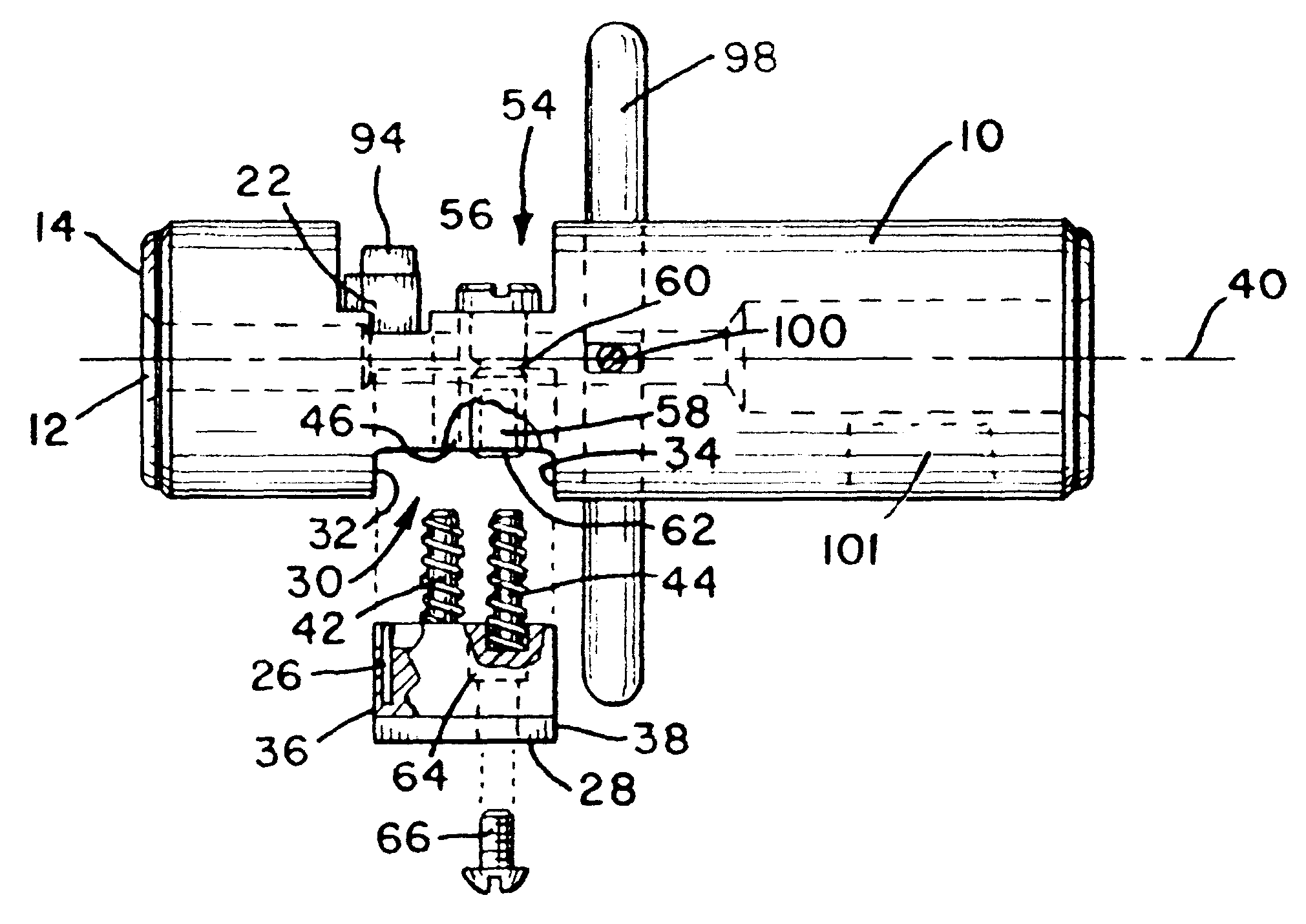
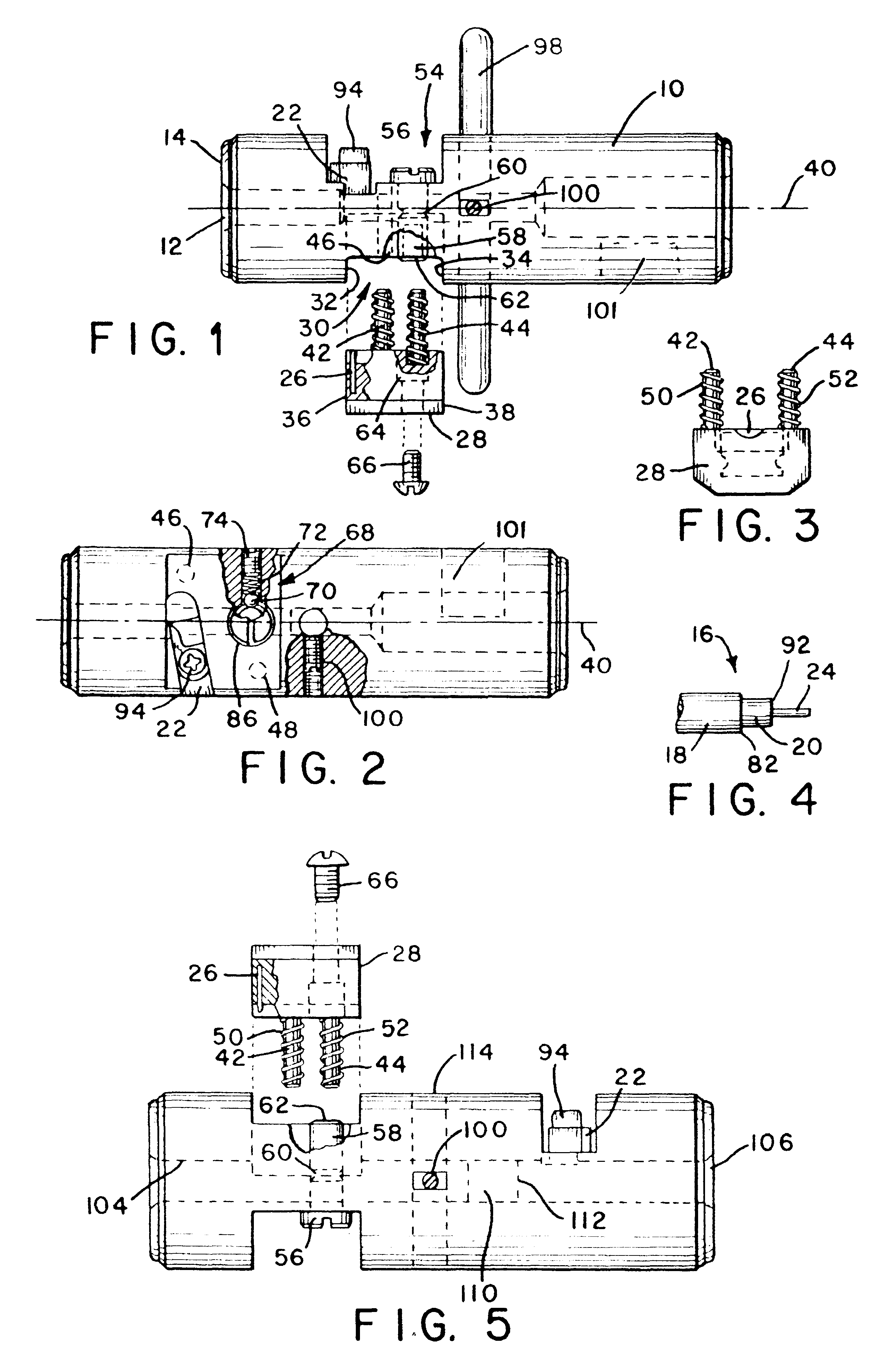
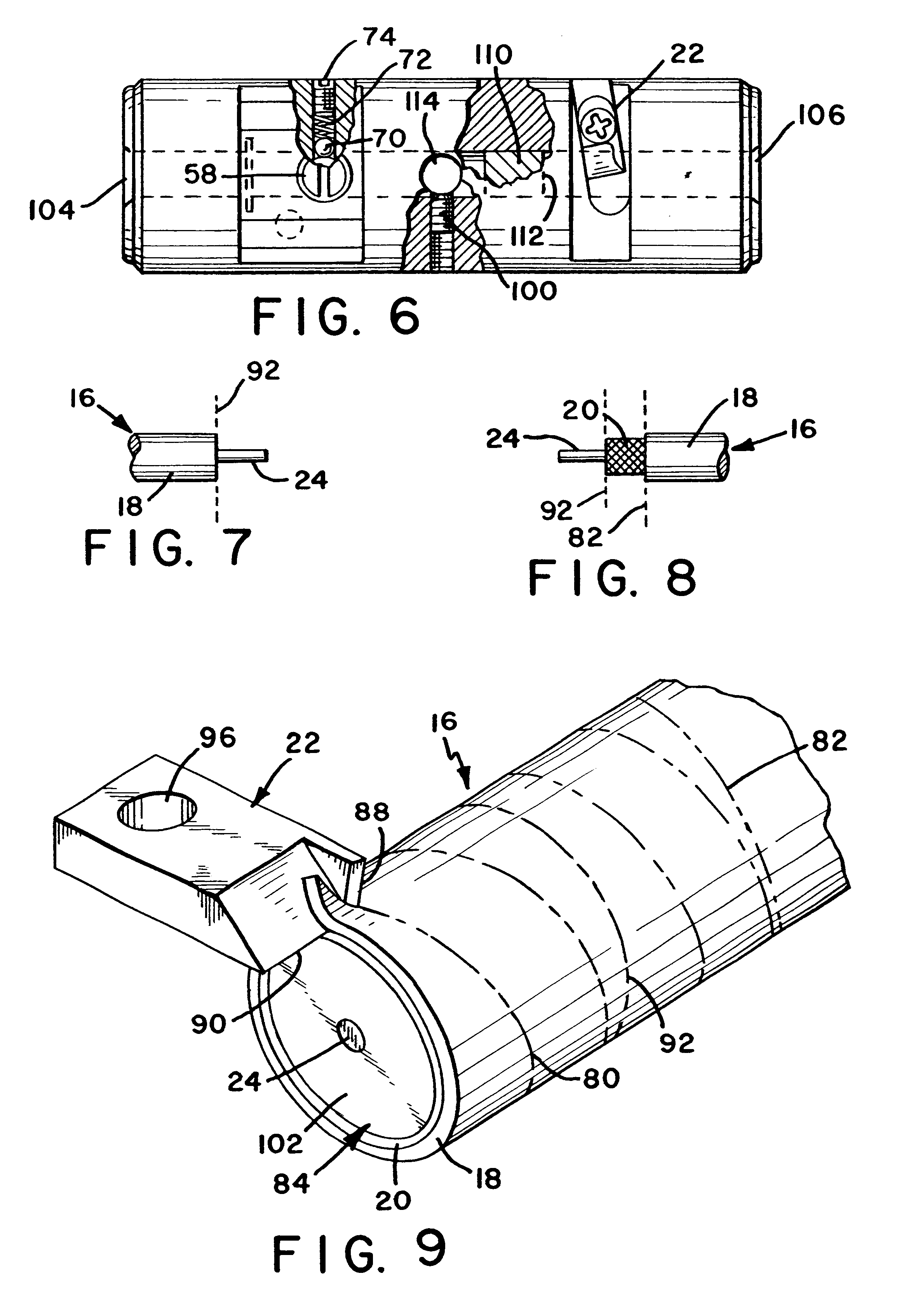
In describing the preferred embodiment of the present invention, reference will be made herein to FIGS. 1-9 of the drawings in which like numerals refer to like features of the invention.

Referring to FIG. 1, the coaxial cable stripping tool of the present invention includes a cylindrical tool body 10 having an axial opening 12 in end 14 of the tool body. As can be seen in FIG. 4, which shows a completed stripping cut, the tool is designed to produce a stepped cut on coaxial cable 16. The coaxial cable includes an outer jacket 18 having an outside diameter just slightly smaller than the inside diameter of axial opening 12, allowing the cable to smoothly enter axial opening 12 where it is supported by the inner walls during cutting.

As the tool is rotated relative to the cable, outer conductor 20 is exposed by a double-edged cutting blade 22 (see FIG. 2), which removes only the outer jacket 18. The cut required to expose inner conductor 24 is made by a planar cutting blade 26 (see FIG...


PUM

PropertyMeasurementUnit
sizesaaaaaaaaaa
conductiveaaaaaaaaaa
distanceaaaaaaaaaa

Abstract

A tool for removing insulation from coaxial cable includes a fixed double-edged cutting blade mounted on the tool body and a planar cutting blade that is mounted on a cassette to move perpendicular to the axis of the cable between a cutting position and a non-cutting position. The double-edged cutting blade includes a transverse cutting edge and a longitudinal cutting edge, the transverse cutting edge lying in a plane substantially perpendicular to an axis of the cable and the longitudinal cutting edge lying in a plane substantially parallel to the axis of the cable. The planar cutting blade has a cutting edge lying in a plane substantially perpendicular to the axis of the cable. The blades may be mounted on the same end of the tool, requiring that the coaxial cable be inserted only once into the tool, or on opposite ends of the tool.

Description

1. Field of the InventionThe present invention relates to stripping tools for removing insulation from coaxial cables prior to the attachment of an electrical connector.2. Description of Related ArtCoaxial cables are widely used to distribute many different kinds of signals, such as video and data signals, and come in a wide variety of designs and sizes. The most common type of coaxial cable includes a center conductor surrounded by an inner layer of insulation and an outer conductor protected with an outer plastic jacket.However, there are many different cable designs and many different types of materials that may be used for the conductors, the insulation and the jacket. The center conductor is most often a solid wire conductor, such as copper or aluminum. However, the outer conductor may be a wire braid, a metallic foil or a metallized tape such as a mylar or other metallized plastic film. The outer conductor may also be constructed with up to four or more different layers in var...

Claims


Application Information

Patent Timeline
Patent Type & Authority Patents(United States)
IPC IPC(8): H02G1/12
CPCH02G1/1221H02G1/1226
Inventor TARPILL, ANDREW J.
Owner RIPLEY TOOLS
Why Eureka
Try Eureka