Commonly, in prior mask configurations, a good mask-to-
face seal has been attained in many instances only with considerable discomfort for the user.
This problem is most crucial in those applications, especially medical applications, that require the user to wear such a mask continuously for an extended periods of time, such as hours or perhaps even days.
In such situations, the user may not tolerate wearing the mask for long durations, and, as a result, optimum therapeutic or diagnostic objectives will not be achieved, or will be achieved with great difficulty and considerable user discomfort.
However, if the seal fit is not good, there will be gaps in the seal-to-face interface, and excessive force will be required to compress the seal member to attain a satisfactory seal in those areas where gaps occur.
Such excessive force is unacceptable, as it produces
high pressure points elsewhere on the face of the user where the mask seal contour is forcibly deformed against the face to conform to the user's facial contours.
This will produce considerable user discomfort anywhere the applied force exceeds the local
perfusion pressure, which is the pressure that is sufficient to
cut off surface
blood flow.
The problem of seal
contact force exceeding desirable limits is even more pronounced when the
positive pressure of the gas being supplied is relatively high or is cyclical to high levels.
This produces high localized pressure on the face, not only in the zone of the mask seal but at various locations along the extent of the retention straps as well.
This too will result in severe discomfort for the user after only a brief period of time.
Even in the absence of excessive localized pressure points, the tight mask and headstraps often may become extremely uncomfortable and user discomfort may well cause discontinued cooperation with the
regimen.
There are two potential limitations of the above described mask type having a sealing flap characteristic.
If the match is not good, the seal will be ineffective.
Second, the normal response of one applying the mask to a user's face is to push the mask harder against the user's face if the mask does not seal.
With the typical flap seal-type mask, increasing
contact pressure against the user's face will not help to form an effective seal if the flap seal does not initially fit well to the facial contours.
It may, however, lead to patient discomfort and other problems as described above.
Some of the principal problems one encounters when trying to apply the self-sealing flap concept to the design of the
respiratory mask are related to the location of relative low points and high points in the facial contours of the user relative to the shape or contour of the flap seal surface.
If the seal surface does not contact the user's face at the relative lower points, then
excessive gas leakage will occur, thus preventing sufficient internal
gas pressure to develop to activate the sealing action of the seal flap at the low points.
In other
breathing mask applications, such as a clinical use, where economic considerations may dictate a mask having the capability to accommodate a wide variety of facial sizes and contours, prior flap type seal structures have not generally been able to provide the requisite versatility.
A related problem with flap seal mask structures concerns the high points of the user's face, where the seal flap may tend to distort or collapse and fold in on itself, thus creating a channel for gas leakage, when pressure is applied in order to effect a seal at adjacent relative low points on the user's face.
Even where the section thickness of the seal flap is very thin, and the material is very soft and flexible, the internal
gas pressure cannot overcome such seal flap
distortion to provide the desired self-sealing.
Despite its general
efficacy in affording a desired seal against the typical user's face, the construction of the inturned flexible flap is such that the contours of certain users'faces may preclude reliable sealing by masks of this type.
This arrangement, however, exerts localized pressure on the user's face which, in turn, results in increased user discomfort.
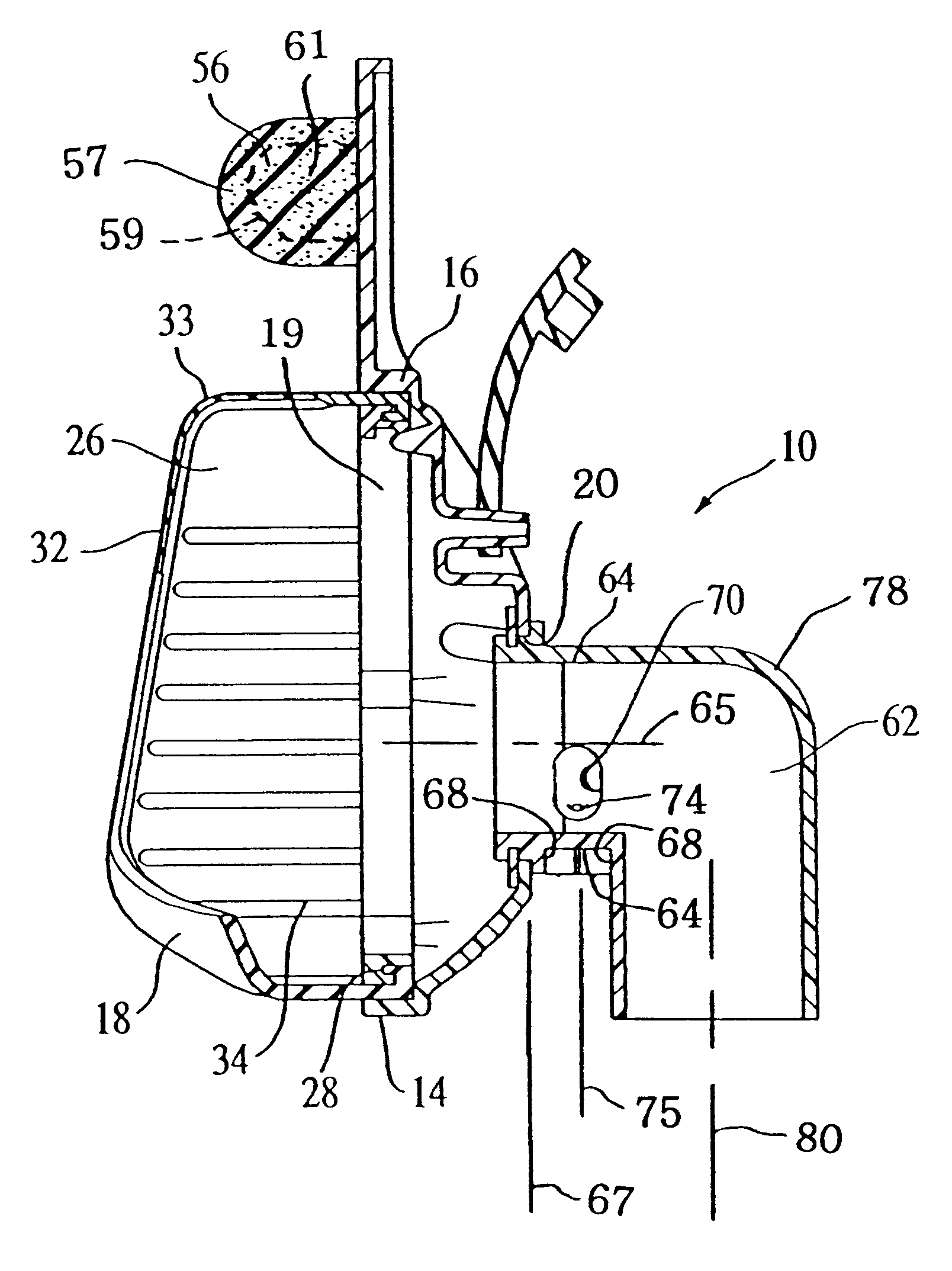
Such perimeter seals are required because the mask seal bodies are over-sized to accommodate, but not contact, the user's
nose.
However, a
disadvantage exists with known forehead spacer /
cushion elements in that multiple forehead pad sizes, mechanically complicated or cumbersome adjustment mechanisms, or both are currently required to accommodate various
patient physical profiles.
However, several drawbacks have been found to be associated with ports in the body of the mask.
For example, air exiting the mask ports may create
noise near the user's face, blow on the patient causing discomfort, or blow on the patient's
bed partner.

