Apparatus and method for venting hydrogen from an electrolytic cell

a technology of electrolysis cell and apparatus, which is applied in the direction of electrolysis components, chemistry apparatus and processes, manufacturing tools, etc., can solve the problems of hydrogen gas accumulation in the headspace of the electrolytic cell

Inactive Publication Date: 2002-10-22
EVOQUA WATER TECH LLC
View PDF3 Cites 44 Cited by
  • Summary
  • Abstract
  • Description
  • Claims
  • Application Information

AI Technical Summary

Problems solved by technology

Often this results in an accumulation of hydrogen gas in the headspace of the electrolytic cell.

Method used


Image

  • Apparatus and method for venting hydrogen from an electrolytic cell
  • Apparatus and method for venting hydrogen from an electrolytic cell
  • Apparatus and method for venting hydrogen from an electrolytic cell

Examples


Embodiment Construction

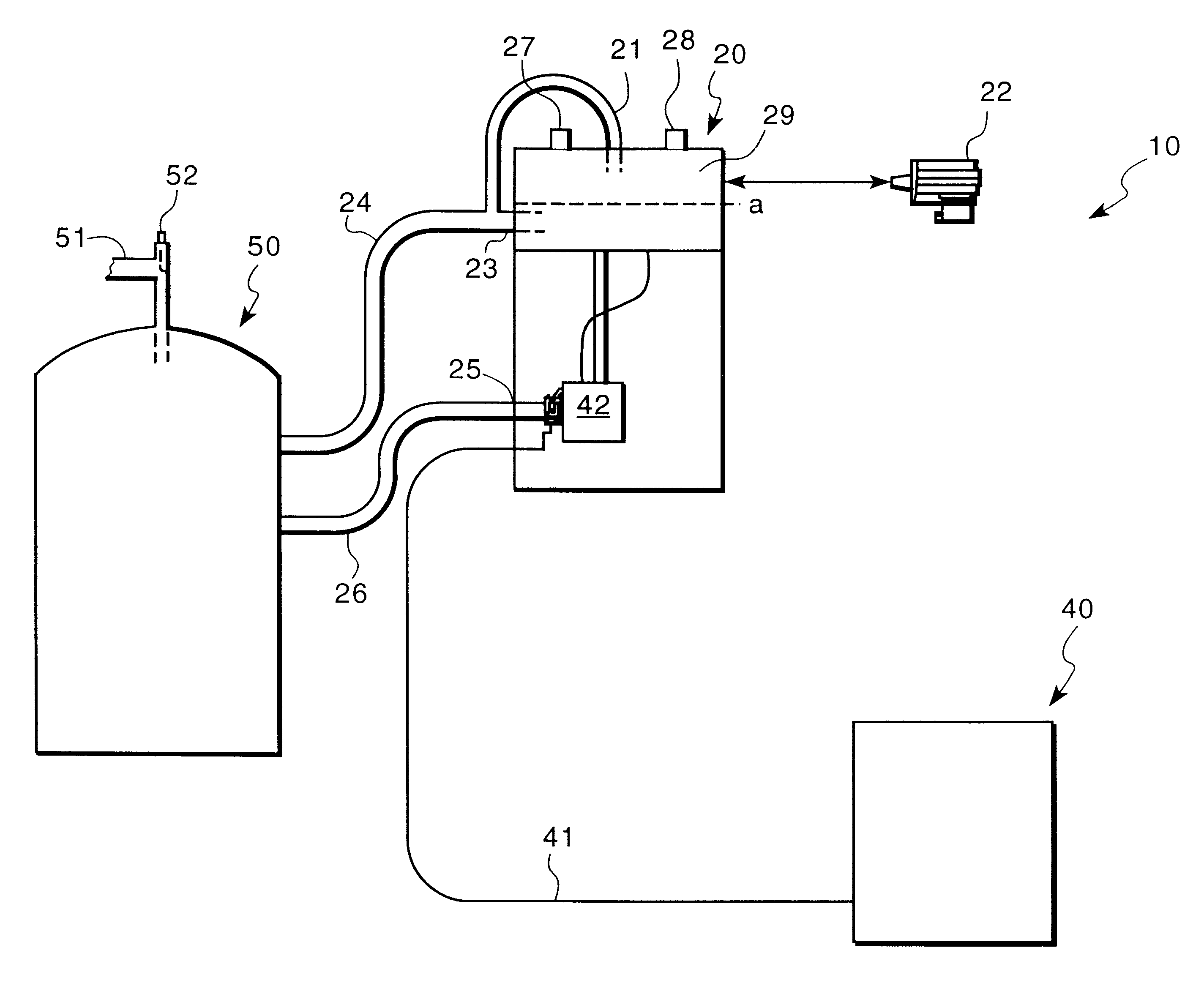
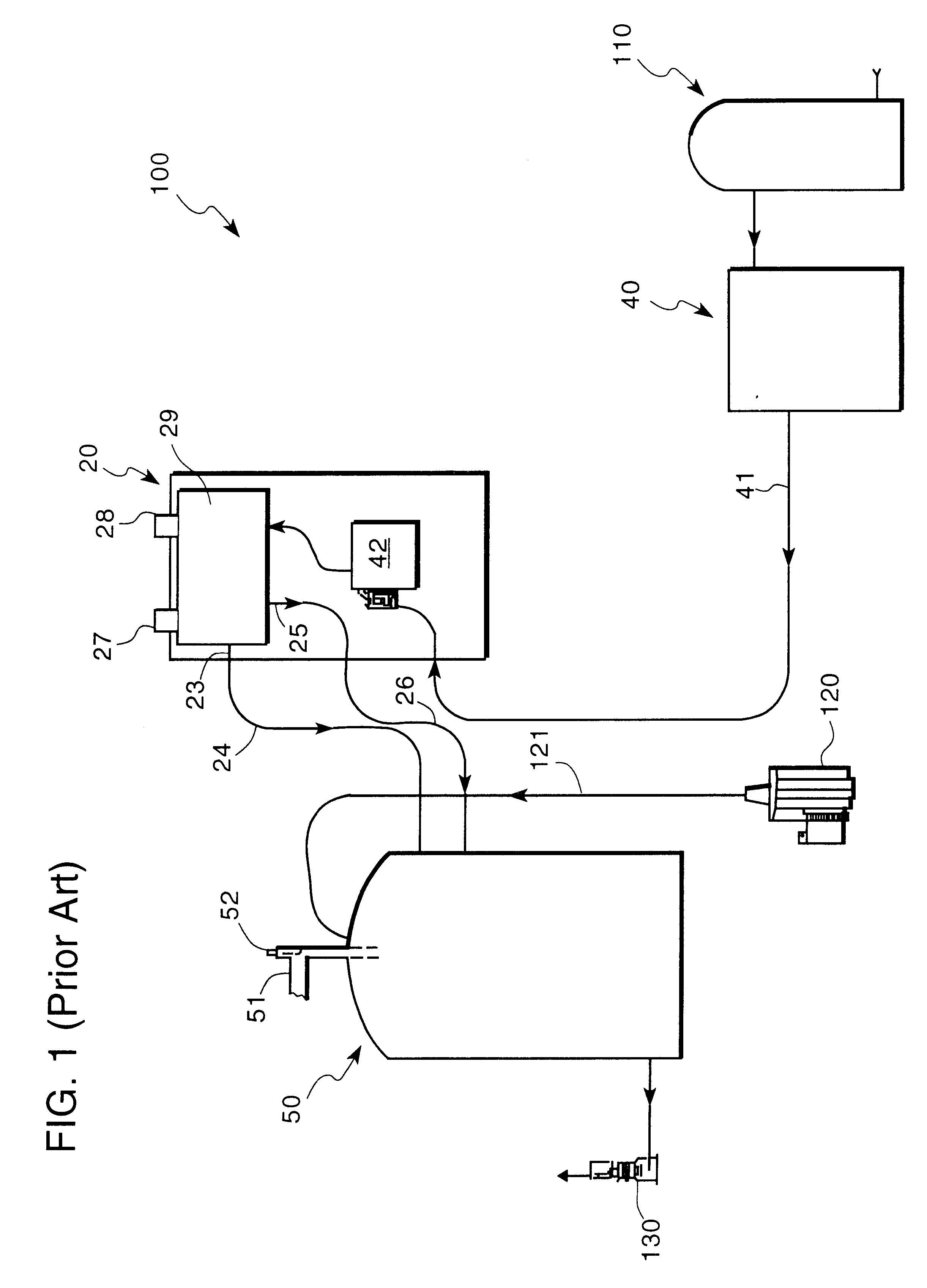
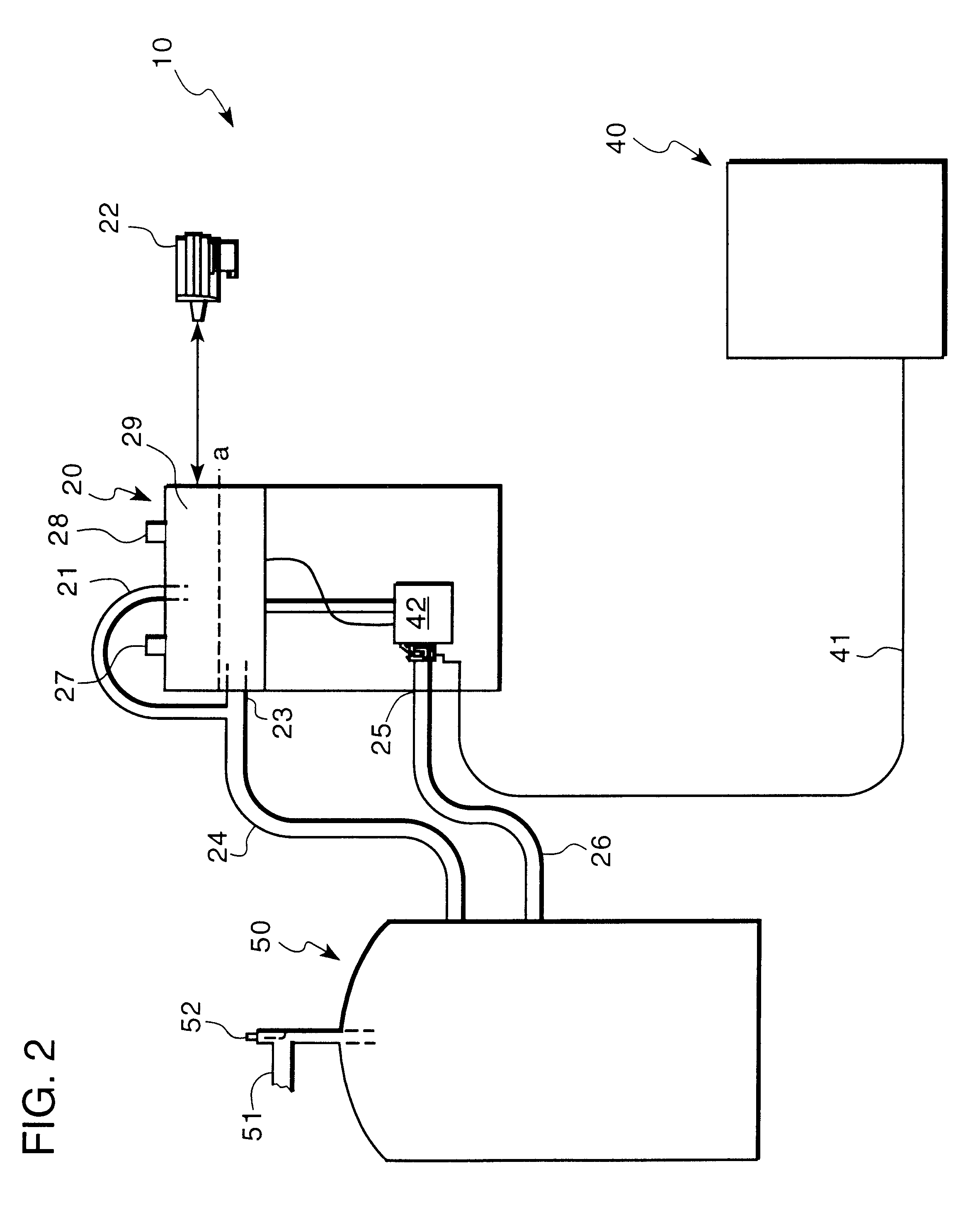
An OSEC.RTM.-LC three-celled electrolytic sodium hypochlorite production system (United States Filter Corporation, Palm Desert, Calif.) was retrofitted to evaluate one aspect of the invention. The system was configured to produce about 26.4 pounds of chlorine, as hypochlorite, per day. Saturated brine solution containing about 30% chloride was diluted by 90% with softened water to obtain a brine solution containing approximately 3% sodium chloride. The system was operated at 224 amps at about 3.1 V per cell, or about 9.3 V total for the 3-cell electrolyzer.

As hypochlorite production is not 100% efficient, the amount of hydrogen produced could not be accurately calculated based on the amount of chlorine produced and instead of producing a theoretical 5.5 SCF of hydrogen per pound of chlorine produced, it was found that about 9.1 SCF of hydrogen were evolved per pound of chlorine. Thus, to obtain the goal of diluting the hydrogen to about 1% by volume in air, air was fed through the s...


PUM

PropertyMeasurementUnit
LELaaaaaaaaaa
heightaaaaaaaaaa
heightaaaaaaaaaa

Abstract

An apparatus and method for venting hydrogen from an electrolytic cell. A brine solution is supplied to an electrolytic cell where hypochlorite and hydrogen gas are produced. A non-combustible gas is introduced into the electrolyzer containing the electrolytic cell and the concentration of hydrogen in the electrolyzer is reduced to a concentration below the LEL of hydrogen.

Description

1. Field of the InventionThe present invention relates to an apparatus and method for venting hydrogen from an electrolytic cell and, more particularly, to an apparatus and method for venting hydrogen from a system producing hypochlorite by electrolysis.2. Description of the Related ArtVarious techniques are available for disinfecting a water supply. Common among these methods is the addition of chemical disinfectants, primarily oxidants, to reduce the microbial content of water. Chlorine, in various forms, is a widely used oxidant, and several techniques exist for introducing it into a water supply. For example, chlorine gas may be injected directly into water, or a solution of hypochlorite (OCl.sup.-), the anion of hydrolyzed chlorine, may be added to the water. Hypochlorite solution may be produced on site and added on demand to the water being treated. The ability to produce a hypochlorite solution locally makes this technique particularly attractive and economically efficient.O...

Claims


Application Information

Patent Timeline
Patent Type & Authority Patents(United States)
IPC IPC(8): C25B15/08C25B1/26C25B1/00C25B15/00C02F1/461C02F1/467
CPCC25B1/26C25B15/08C02F1/46104C02F1/4674
Inventor BRYAN, JARED K.STOCKINGER, GREGORY E.PARIKH, MANOR M.
Owner EVOQUA WATER TECH LLC
Why Eureka
Try Eureka