
Method for transmitting collision-free messages in a digital selective call signaling protocol

a signaling protocol and digital selective technology, applied in the field of transmission of collision-free messages in a digital selective call signaling protocol, can solve the problems of high traffic load, communication device postpone acquisition of channels, and inefficient use of communication devices under high traffic load

Inactive Publication Date: 2002-10-22
GOOGLE TECH HLDG LLC
View PDF4 Cites 35 Cited by
  • Summary
  • Abstract
  • Description
  • Claims
  • Application Information

AI Technical Summary

Problems solved by technology

If activity is detected, the communication device postpones acquisition of the channel according to a random delay.
If upon transmitting the message a collision is detected, the communication device terminates transmission, and postpones acquisition of the channel according to a random delay.
It should be apparent that the potential for collisions in the decentralized communication systems described above makes their use inefficient under high traffic loads.
This is especially a problem in systems where a short latency is desirable.
Centralized communication systems also may insert unnecessary latency into a lightly loaded system.

Method used


Image

  • Method for transmitting collision-free messages in a digital selective call signaling protocol
  • Method for transmitting collision-free messages in a digital selective call signaling protocol
  • Method for transmitting collision-free messages in a digital selective call signaling protocol

Examples


Embodiment Construction

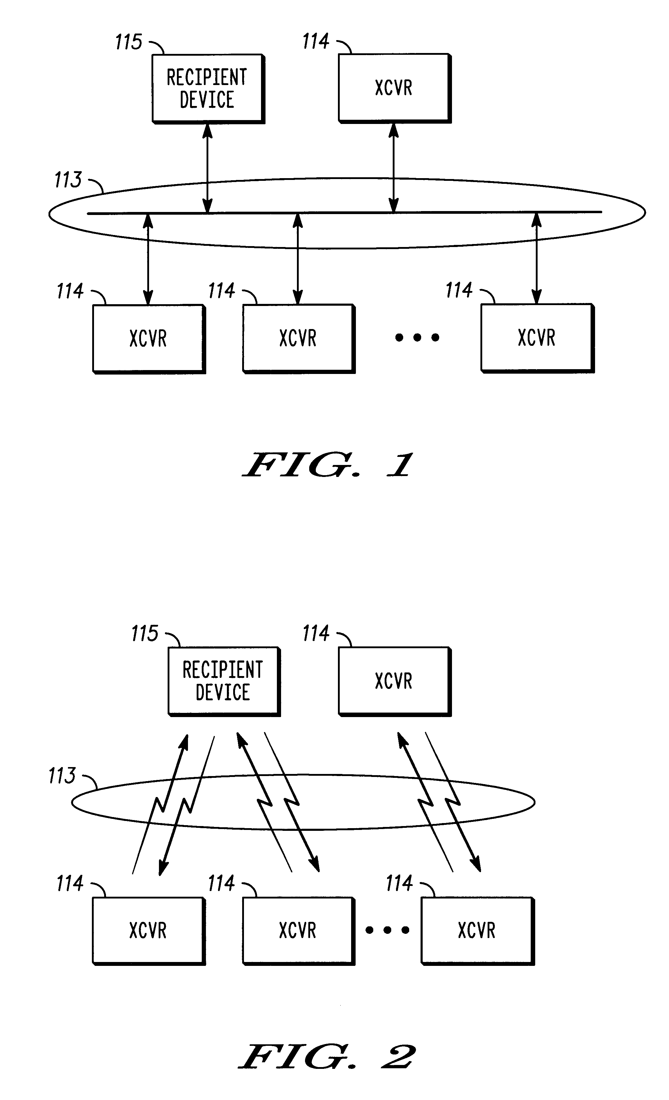
FIGS. 1-2 show alternative embodiments of a communication system, each depicted by an electrical block diagram, according to the present invention. A first embodiment of the communication system shows a plurality of wireline transceivers 114 interconnected by way of a wireline communication medium 113. The second embodiment shown in FIG. 2 is analogous to the system illustrated in FIG. 1 with the exception that the transceivers 114 and the communication medium 113 are wireless. In both of these embodiments, a transceiver 114 is selected for communicating with a recipient communication device 115, which is capable of one-way or twoway communication.

The recipient communication device 115 may comprise any one of several embodiments. In one instance, for example, the recipient communication device 115 may comprise a targeted one of the transceivers 114. In another instance, the recipient communication device 115 may comprise a conventional portable and battery-operated SCR (Selective Ca...


PUM


Abstract

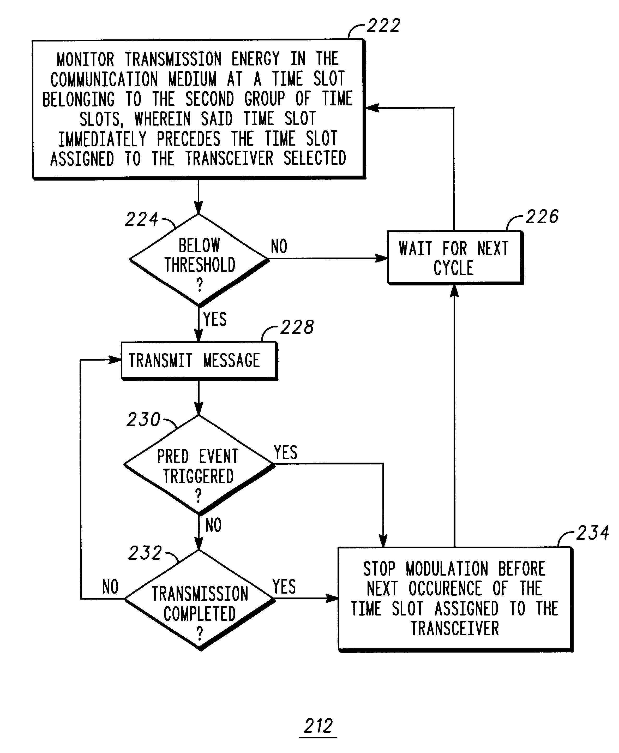
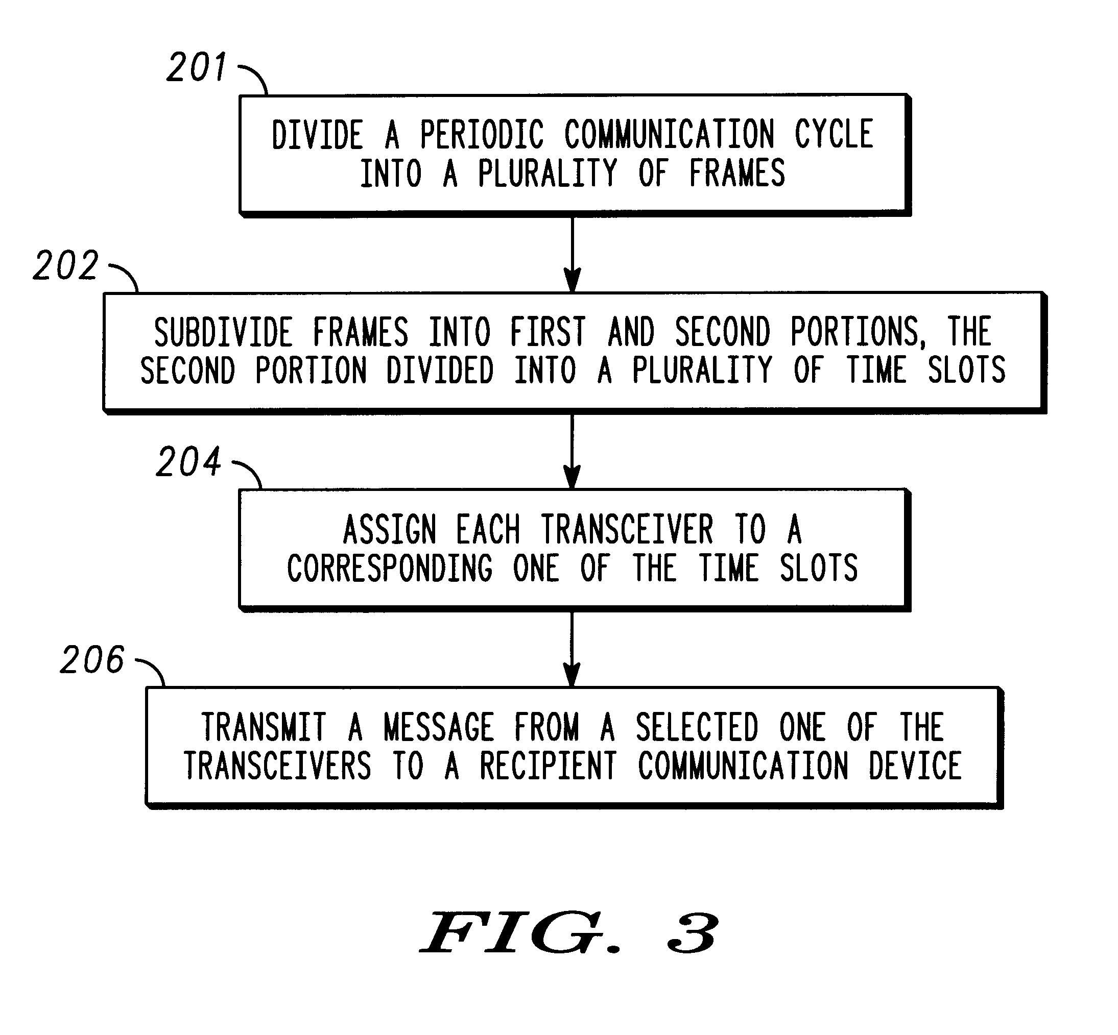
A plurality of transceivers (114) each include a transceiver circuit (409), and a processing system (412) coupled to the transceiver circuit. A periodic communication cycle is divided into a plurality of frames, each frame having a predetermined interval. Each of the plurality of frames in turn is subdivided into first and second portions (301, 303), whereby the second portion is used by the transceivers for requesting access to a communication medium (113). The second portion is further subdivided into a plurality of time slots, each time slot having a duration equal to or greater than a predetermined propagation delay of a signal transmitted between transceivers. Each of the transceivers is assigned to a corresponding one or more of the time slots. When transmitting a message from a selected one of the transceivers to a recipient communication device (115), the processing system of the transceiver selected is adapted to enable the transceiver circuit to monitor transmission energy in the communication medium during a time slot immediately preceding the time slot assigned to the transceiver selected (208, 210, 212), and if the energy measured is below a predetermined threshold, cause the transceiver circuit to transmit at least a portion of the message to the recipient communication device beginning at the time slot assigned to the transceiver selected (214, 216, 218, 220).

Description

This invention relates in general to communication systems, and particularly, to a method for transmitting collision-free messages in a digital selective call signaling protocol.RELATED INVENTION (S)The present invention is related to the following invention which is assigned to the same assignee as the present invention:Ser. No. 09 / 301,679 mailed Mar. 31, 1999, by Xie et al., entitled "Method for Transmitting Collision-Free Messages in a Communication System and Apparatus Therefor."Presently, there are many medium access protocols in existence for exchanging messages between decentralized communication devices utilizing a common channel. Ethernet is an example of a commonly used communication protocol in decentralized local area networks. Aloha is another.Ethernet networks employ a channel acquisition technique generally known as CSMA / CD, which stands for Carrier Sense Multiple Access Collision Detection. Essentially, this technique requires a communication device (e.g., a personal...

Claims


Application Information

Patent Timeline
Patent Type & Authority Patents(United States)
IPC IPC(8): H04L12/56H04L12/28
CPCH04W74/0808H04W28/04
Inventor DORENBOSCH, JHEROEN PIETERGUNTIN, EDUARDO
Owner GOOGLE TECH HLDG LLC
Learn More