Broadband coupled-line power combiner/divider

a power combiner and coupled-line technology, applied in coupling devices, electrical devices, waveguides, etc., can solve the problems of increasing the operating bandwidth of the combiner, increasing the insertion loss and complexity, and the real design becomes very complicated

Inactive Publication Date: 2002-10-29
BAE SYST INFORMATION & ELECTRONICS SYST INTERGRATION INC
View PDF5 Cites 43 Cited by
  • Summary
  • Abstract
  • Description
  • Claims
  • Application Information

AI Technical Summary

Benefits of technology

It is another object of the present invention to provide one-section N-Way power combiner with high isolation between its N outputs at two and more octave bandwidth.
It is a further object of the present invention to provide N-Way power combiner having a symmetrical configuration with respect to its inputs to avoid phase and amplitude imbalances.

Problems solved by technology

On the other hand, these devices in most cases are much better for implementation in VHF-UHF bands and extension of their operating bandwidth remains still the open problem.
In cases when N>3 and M>2 (for achieving broad band) the real design becomes very complicated.
However, this way of extending bandwidth implies increasing insertion losses and complexity.
However, if the required bandwidth is two octaves or more, it is impossible to realize acceptable isolation between ports as well as impedance transformation in known one-section structure, and a very complicate power combiner should be used independent on value of built-in impedance transformation ratio.

Method used


Image

  • Broadband coupled-line power combiner/divider
  • Broadband coupled-line power combiner/divider
  • Broadband coupled-line power combiner/divider

Examples


Embodiment Construction

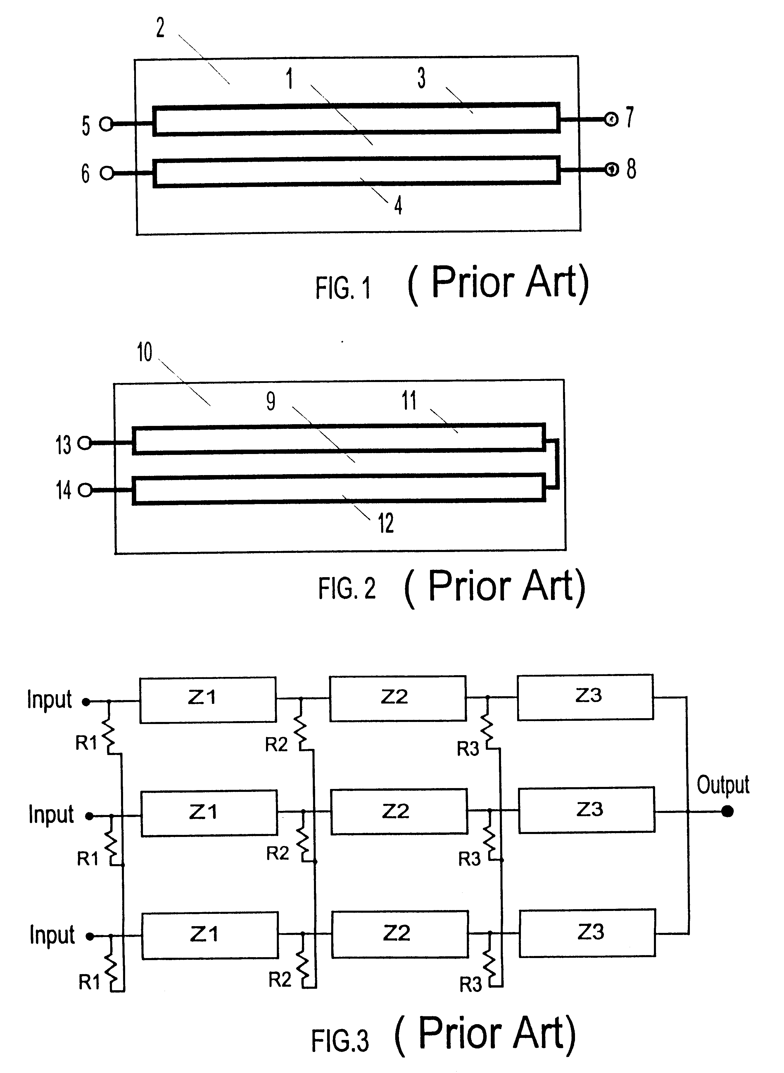
Referring first to FIG. 1, prior art two-conductor coupled transmission lines is indicated generally by number 1. The first line has one conductor 3 and common ground as a second conductor of this line. The second line has one conductor 4 and a common ground 2 as a second conductor of this line. Both lines have equal length and may have equal or different characteristic impedances. Four unbalanced ports of this structure are 5, 6, 7, and 8. If in a particular case both lines are identical, they form matched directional coupler. At a central frequency of this coupler, the electrical length of each line is equal 90 deg. The nominal impedance, the same at each port 5, 6, 7, 8, and coupling ratio are determinates by coupling coefficient between lines and their characteristic impedance. If coupling coefficient is equal 0.707, a standard 3-dB coupler is provided.

When two adjacent matched ports (5 and 6) or (7 and 8) of coupler FIG. 1 are connected, a matched two-port without impedance tra...


PUM


Abstract

A broadband coupled-line N-way power combiner is presented for combining N RF signals into a common load. This combiner includes N>=2 input ports, a common output port, and N identical at least two-conductor coupled transmission lines, and N isolating resistors. Each of these two-conductor coupled transmission line has at one end one conductor connected to one of the input port of the power combiner, and another conductor connected to the common output port. At another end two conductors of each two-conductor coupled transmission line are terminated to one of the N isolating one-ports.

Description

The present invention relates in general to power combiners / dividers. More specifically, the invention relates to power combiners / dividers of a coupled transmission line (quarter-wavelength) type that enables significant increases in operating bandwidth.DESCRIPTION OF THE PRIOR ARTPower combiners / dividers are essential subsystems in modem communication, HDTV and other systems, and play a major role in solid-state power amplifiers to achieve the specific output power. The necessary bandwidth of systems is permanently increasing, but on the other side the insertion loss and cost of power combiners should be minimized. There are two principal different technologies, which currently provide broadband power combining / dividing with isolation between ports, namely, transformer-type devices, usually with ferrite cores, to realize multi-octave bandwidth by providing RF isolation of their main operating conductors from ground, and quarter-wavelength (or multiple quarter-wavelength) devices wi...

Claims


Application Information

Patent Timeline
Patent Type & Authority Patents(United States)
IPC IPC(8): H01P5/12
CPCH01P5/12
Inventor LONDON, SIMON Y.
Owner BAE SYST INFORMATION & ELECTRONICS SYST INTERGRATION INC
Why Eureka
Try Eureka