
Process for the irradiation of strand-shaped irradiated material, and an irradiating device for the performance of the said process

a technology of irradiation device and strand-shaped irradiation material, which is applied in the direction of electrical discharge tube, nuclear engineering, therapy, etc., can solve the problems of requiring special equipment, requiring considerable apparatus expenditure, and not being able to use commercially available standard apparatus consisting of source and scanner

Inactive Publication Date: 2002-11-12
RADIATION DYNAMICS INC
View PDF5 Cites 3 Cited by
  • Summary
  • Abstract
  • Description
  • Claims
  • Application Information

AI Technical Summary

Benefits of technology

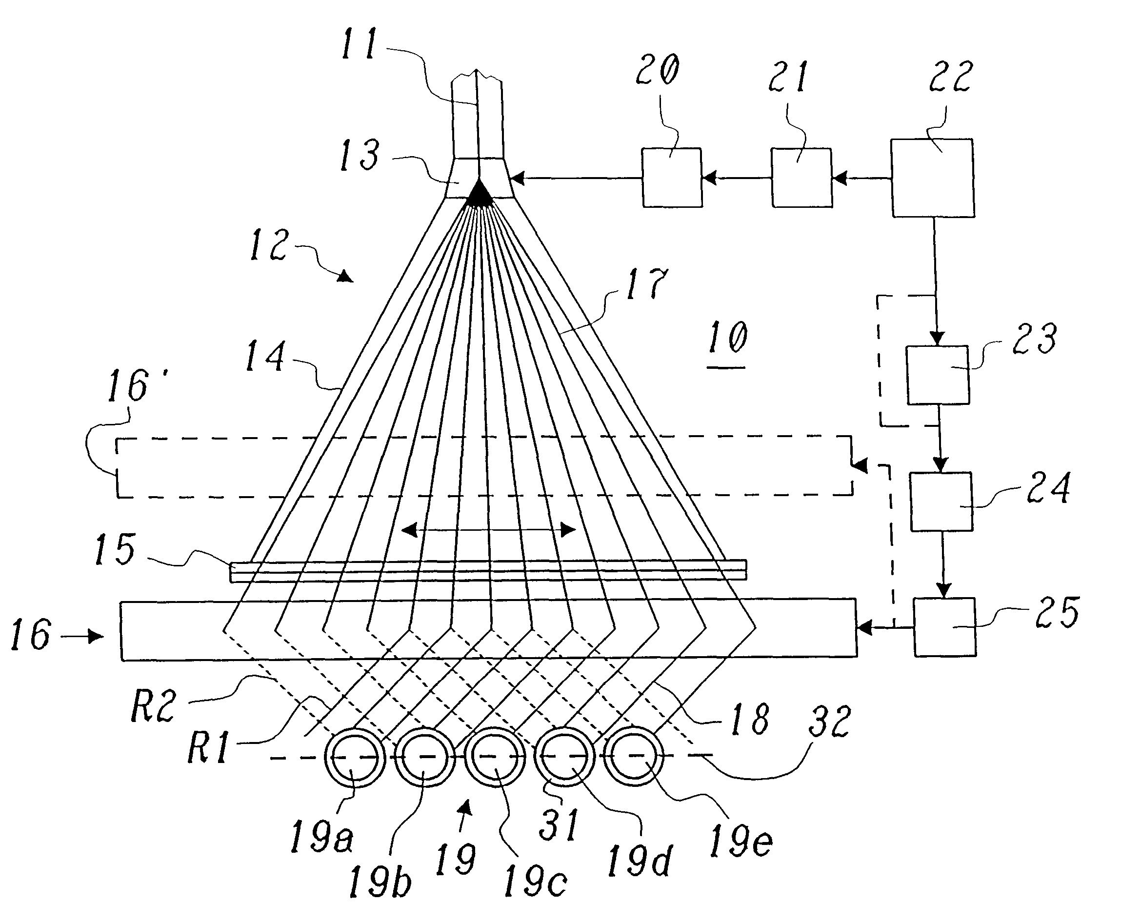
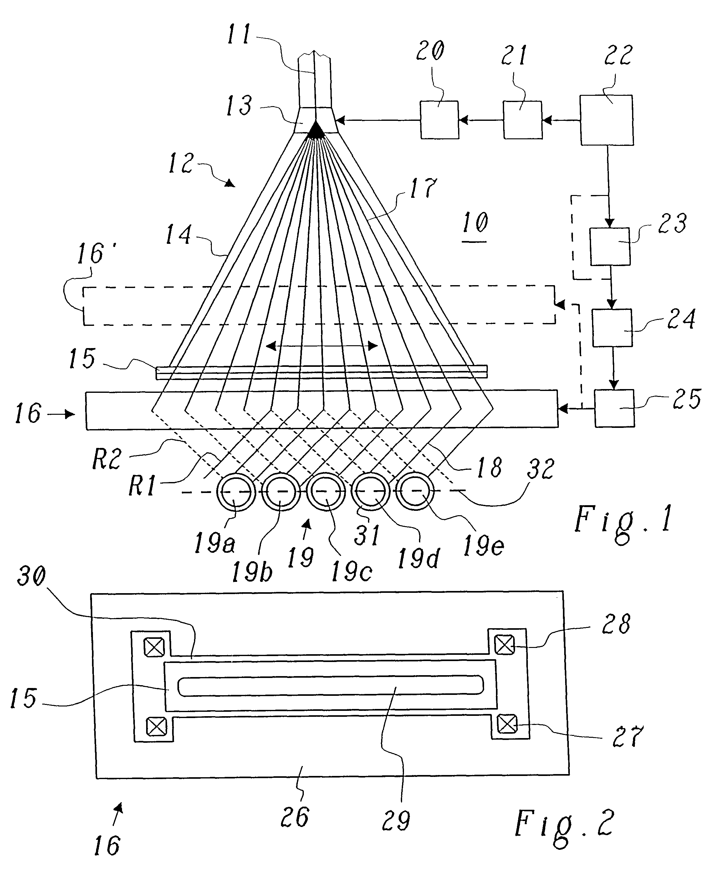
This objective is achieved by a process of the type referred to in the preamble in that a scanned electron beam is created from an electron beam in a scanner by means of a scanning device which creates a radiation fan by means of the temporally-controlled slewing backwards and forwards in a predetermined angle range transversely to the longitudinal direction of the irradiated material, and that the scanned electron beam is deflected by means of a deflector magnet arranged between the scanning device and the irradiated material, for each scanning angle of the radiation field, in such a way that it impinges on the irradiated material which is to be treated from one of the two fixed irradiation devices. The core of the invention lies in the fact that the scanned electron beam, scanned transversely to the longitudinal direction of the irradiated material by means of additional deflection, optionally into the two desired irradiation directions. In this way it is possible, with one single standard piece of apparatus, consisting of electron beam source and scanner, and with only one additional deflection device, to achieve the cross-firing process simply and economically.
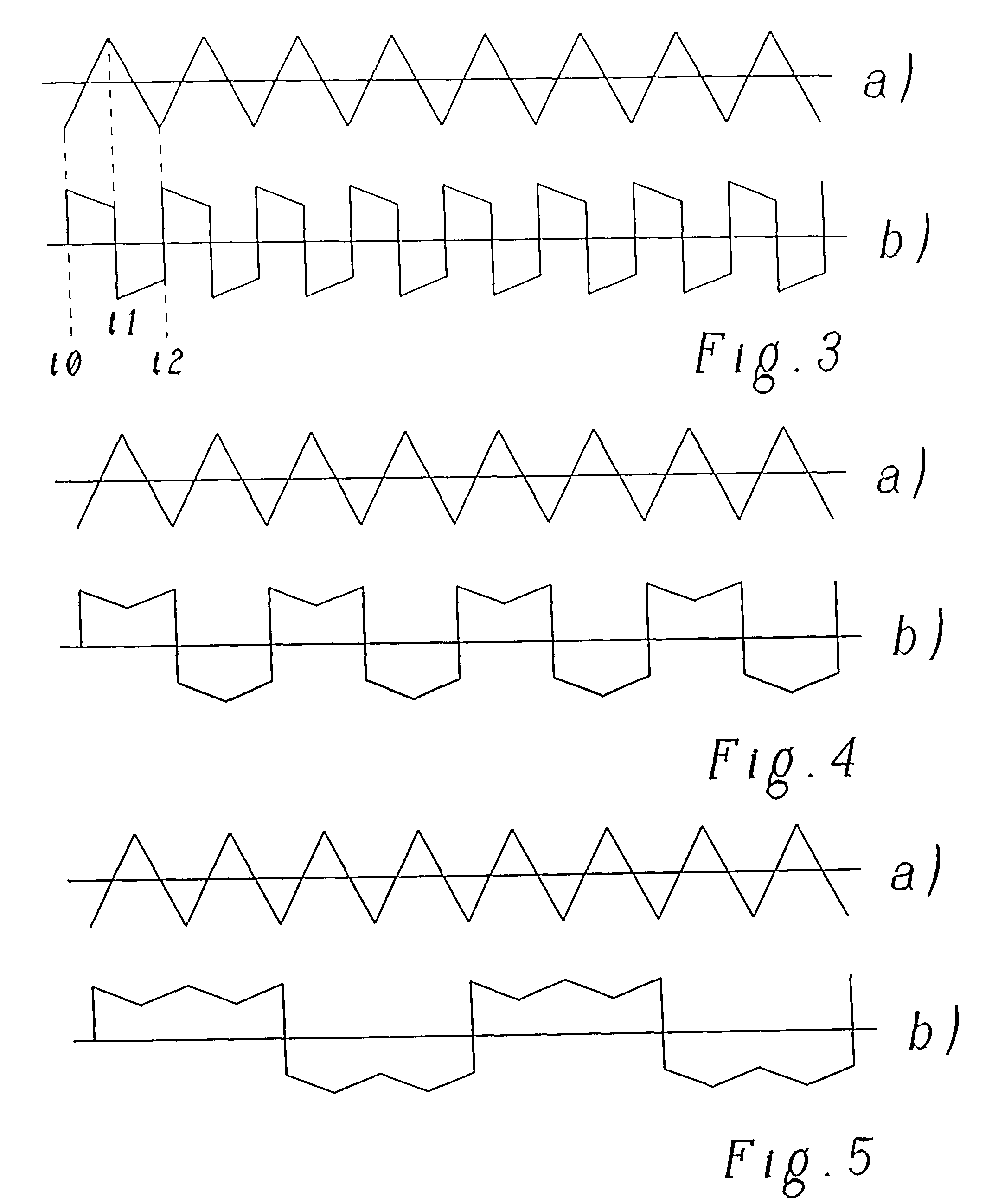
A preferred embodiment of the process according to the invention is therefore characterised in that a controllable electromagnet is used as the deflection magnet, which in the area of the fan-shaped radiation field creates an essentially homogenous magnetic field of controllable magnetic field strength and direction, and that the magnetic field strength and direction are changed synchronously to the deflection of the electron beam in the scan direction of the scanner in such a way that the electron beam deflected in the magnetic field of the deflection magnet impinges on the irradiated material from one of the two irradiation devices. The homogenous magnetic field can be created relatively simply. By the temporal control of the magnetic field strength, it is easily possible, with electronic media, at any time, which simultaneously determines a specific scan angle for the scanned electron beam, at which the beam runs through the scanner, an appropriate deflection angle can be attained in the deflection magnet. If the parameters in the electron source or in the scanner change, the device can be readjusted by simple adaptations in the control device.
A preferred embodiment of the device according to the invention is characterised in that the deflection magnet is an electromagnet capable of being controlled in terms of magnetic field strength and direction, which creates an essentially homogenous magnetic field for the deflection of the scanned electron beam, that actuation media are provided for the deflection magnet, which control the magnetic field strength and direction of the deflection magnet in such a way that the electron beam deflected by the deflection magnet always impinges on the material to be irradiated from one of the two irradiation devices, that the scanner comprises a scan device which is actuated with a scan frequency f.sub.s, created in an oscillator, that the actuation media for synchronisation stand in an operational connection with the oscillator, and that the actuation media comprise a frequency divider and a function generator. With the aid of the frequency divider, switchover between the irradiation directions can be effected at a frequency which is only a fraction of the scan frequency. The function generator allows for the precise control of the temporal sequence of the magnetic field in the deflection magnet.

Problems solved by technology

The cross-firing process has a number of disadvantages, however, in the technical embodiments known hitherto: If, as shown in EP-A1-0 037 869 (FIG. 3), two radiation sources are used with downstream scanners in order to effect the irradiation from both the essentially orthogonal irradiating devices, this implies a considerable expenditure in terms of apparatus, because two vacuum devices, two high-voltage and high-current supplies for the electron beam sources and scanning devices respectively in the scanners, and the pertinent vacuum devices are required.
If, by contrast, as is shown in FIG. 1 of PCT / CH 96 / 00052, the beam is divided from one electron beam source and conducted via separate beam guides to two scanners, which direct the beam in temporal packages onto the irradiated material to be cross-linked from the two irradiating devices, it is at present still not possible to use standard apparatus consisting of source and scanners which is commercially tenable.
Rather, special apparatus must be created, which requires considerable expenditure.

Method used


Image

  • Process for the irradiation of strand-shaped irradiated material, and an irradiating device for the performance of the said process
  • Process for the irradiation of strand-shaped irradiated material, and an irradiating device for the performance of the said process
  • Process for the irradiation of strand-shaped irradiated material, and an irradiating device for the performance of the said process

Examples


Embodiment Construction

The following values can be assumed by way of example for an irradiation device which can be used in cable production:

Deflection magnet

Low structural height (.ltoreq.100 mm) beneath the scanner 12;

As far as possible, parallel B-field in the deflection range with a clear width of 250 mm (air gap 30);

Magnetic induction B in the range from 0.02 to 0.20 Tesla for 3-MeV electrons at a structural height of the deflection magnet 16 of 100 mm;

Cooling of the deflection magnet for preference with air or water.

Overall, the invention provides a new irradiation process and an irradiation device in which, by means of a dynamic "cross-firing" system, and making use of conventional systems and comparatively low additional expenditure, an efficient and uniform irradiation of strand-shaped irradiation materials is possible in a simple manner.


PUM


Abstract

In a process for the irradiation of strand-shaped irradiated material (19; 19a-e), in particular cable insulation or sheathing (31) capable of being cross-linked by irradiation, or tubes, hoses, or profile elements capable of being cross-linked by irradiation, with electron beams impinging transversely to the longitudinal axis of the irradiated material (19; 19a-e), which strike the irradiated material (19; 19a-e) from two fixed irradiation directions (R1, R2), located at an angle to one another which is other than zero and for preference is a right angle, a uniform irradiation is achieved in a simple manner in that a scanned electron beam (17) is created from an electron beam (11) in a scanner (12) by means of a scan device (13), which by means of a temporally-actuated back-and-forth slewing movement in a prescribed angle range creates a radiation fan transversely to the longitudinal direction of the irradiated material, and that the scanned electron beam (17) is deflected by a deflection magnet (16, 16') arranged between the scan device (13) and the irradiated material (19; 19a-e) in such a way for each scan angle of the irradiation field that it impinges on the irradiation material (19; 19a-e) to be treated from one of the two fixed irradiation directions (R1, R2).

Description

TECHNICAL SECTIONThe present invention relates to the sector of irradiation using electron beams. It further relates to a process for the irradiation of strand-shaped irradiated material, and in particular cable insulation or sheathing capable of cross-linking by radiation, or tubes, hoses, or profile elements capable of cross-linking by radiation, with electron beams impacting transversely to the longitudinal axis of the irradiated material, which impact on the irradiated material from two fixed irradiating devices located at an angle to one another which is other than zero degree, and for preference is a right angle.It further relates to an irradiating device for the performance of the said process, which comprises first media for the generation of an electron beam, and second media which direct the electron beam form the two irradiating devices onto the bodies which are to be irradiated. Such a process and such a device are known, for example, from the earlier patent application ...

Claims


Application Information

Patent Timeline
IPC IPC(8): H01J37/147H01J33/00H01J33/02
CPCH01J33/02H01J37/1475
Inventor GIELENZ, GERHARDSCHMID, BRIGITT
Owner RADIATION DYNAMICS INC
Learn More