

Apparatus for entering data into a computer
a computer and data technology, applied in computing, instruments, electric digital data processing, etc., can solve the problems of inefficient design use of desktop space, affecting the reducing the response and usefulness of such a device,
- Summary
- Abstract
- Description
- Claims
- Application Information
AI Technical Summary
Problems solved by technology
Method used
Image

Examples
first embodiment
the Invention
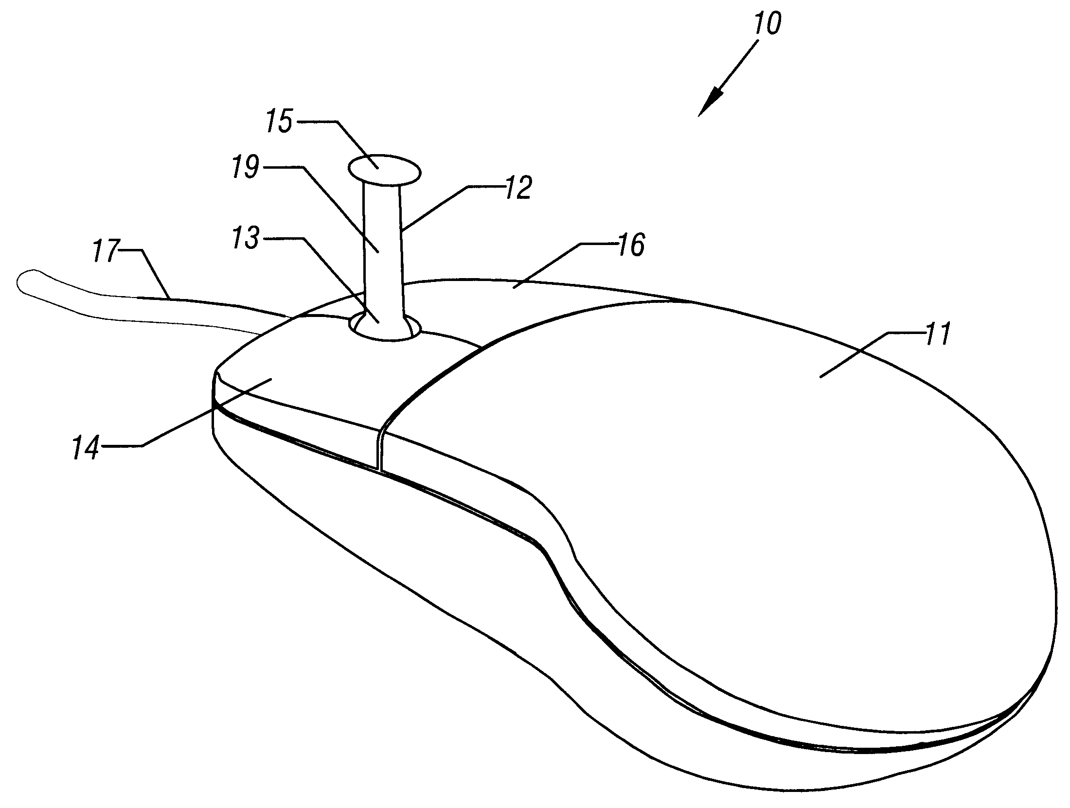
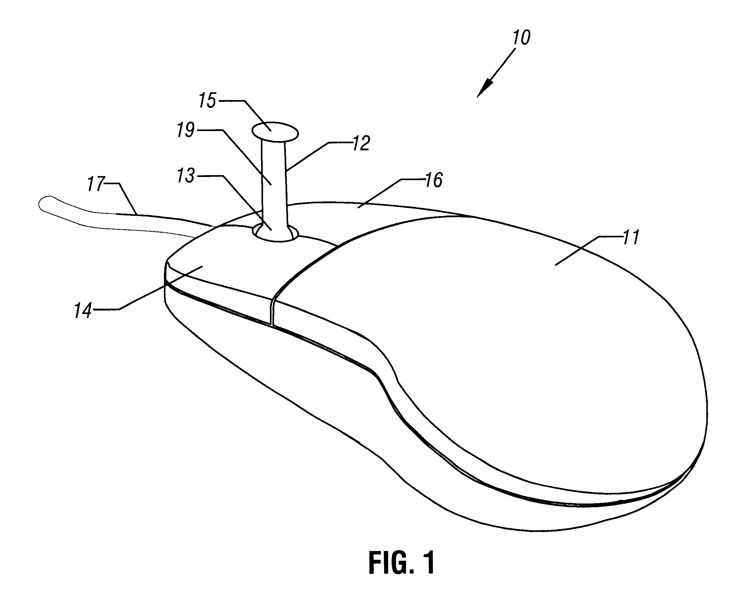
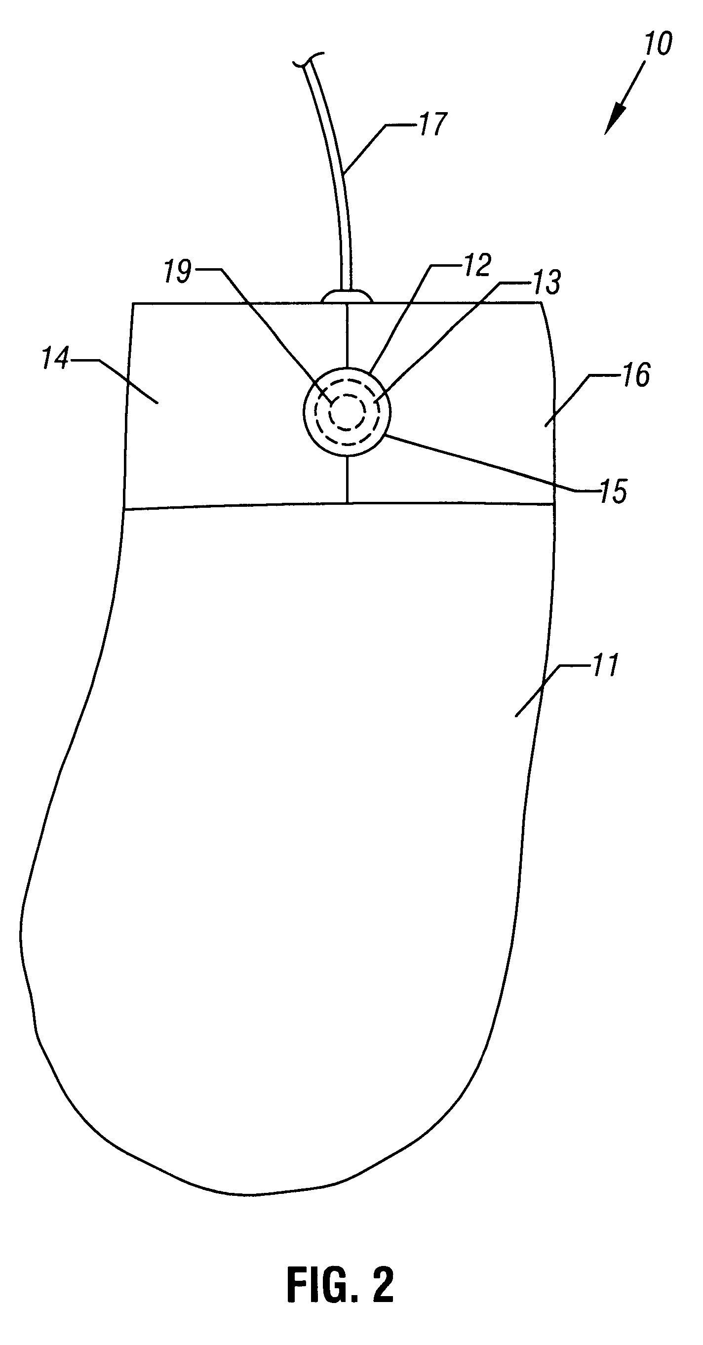
In accordance with a first embodiment of the invention, a computer pointing device or joystick integrated mouse (JIM) 10 is shown in a perspective view in FIG. 1 and a top view in FIG. 2. The JIM 10 includes a housing 11, a joystick or lever 12 (which may be elongated as shown), buttons 14 and 16, and a mouse cord, line, or cable 17. The housing mechanically supports the buttons 14 ("left mouse button") and 16 ("right mouse button"), as well as the lever 12. The lever 12 is mechanically coupled to the housing 11 at a pivot end 13. The pivot end 13 allows the lever 12 to be pivoted by a thumb or finger(s) touching an extended end 15, or along its shaft 19. The lever 12 may be positioned and supported by the housing 11 between the mouse buttons 14 and 16. The pivot end 13 may have any suitable structure and mechanism known in the art. For example, the pivot end 13 may be a ball in a ball and socket arrangement, with the socket formed in the housing 11.
The housing 11 encas...
second embodiment
the Invention
A JIM 10' is shown in a perspective view in FIG. 4 in accordance with a second embodiment of the invention. The JIM 10' has all the features and functionality of the JIM 10 in FIGS. 1-3, but includes additionally a mouse button 18 which operates similar to, and has the same functionality as, the mouse button 14 (the "left-hand" mouse button). In FIG. 4, the mouse button 18 is located on the right-hand thumb side 21a of the device 10', and is mechanically supported on the side 21a by the housing 21 (the housing 21 is functionally analogous to the housing 11 of the JIM 10). A user may depress the button 18 instead of the button 14 to send the same or similar left button output signals to the computer (not shown) via cable 17.
Other than the additional button 18 and its coupling to the same circuitry (not shown) that generates these signals in the JIM 10', the JIM 10' has similar structural and connectivity features as the JIM 10 in FIGS. 1-3. As with the JIM 10, although t...
third embodiment
the Invention
FIGS. 5a-5b and 6 illustrate a third embodiment of the invention, JIM 10", employing retractable feet 20. Other than the feet 20, the JIM 10" includes all of the features and functionality of the JIM 10. As shown in FIGS. 5a-5b, although this particular embodiment does not include the side mouse button 18 as in the second embodiment (JIM 10') described above, the side mouse button 18 could be included along with its associated signal-generating and transmitting electronic circuitry (not shown). FIG. 5a shows the feet 20 in their extended position and FIG. 5b shows the feet 20 in their retracted position above a surface or desk 24.
Referring to FIG. 6, a view of an underside 31b of a housing 31 of the JIM 10" reveals the extendible / retractable "feet" 20 in their extended position (the housing 31 is functionally analogous to the housing 11 of the JIM 10). As shown in the side view in FIG. 5a, the feet 20 can be extended to disengage a ball 22a of a trackball unit 22 (shown...
PUM
 Abstract
Description
Claims
Application Information