
Graphics system having a super sampled-sample buffer with efficient storage of sample position information

a graphics system and buffer technology, applied in the field of computer graphics, can solve the problems of increasing the complexity and amount of data being sent to the display device, the incorporation of graphics processors with a great deal of processing power, and the complexity of images displayed now more complex

Inactive Publication Date: 2002-11-19
ORACLE INT CORP
View PDF24 Cites 3 Cited by
  • Summary
  • Abstract
  • Description
  • Claims
  • Application Information

AI Technical Summary

Problems solved by technology

Modem graphics systems, however, incorporate graphics processors with a great deal of processing power.
This change is due to the recent increase in both the complexity and amount of data being sent to the display device.
Similarly, the images displayed are now more complex and may involve advanced techniques such as anti-aliasing and texture mapping.
As a result, without considerable processing power in the graphics system, the CPU would spend a great deal of time performing graphics calculations.
This could rob the computer system of the processing power needed for performing other tasks associated with program execution and thereby dramatically reduce overall system performance.
While this extra performance may be useable in multiple-viewer environments, it may be wasted in more common primarily single-viewer environments.
For example, an image with a high pixel density may still appear unrealistic if edges within the image are too sharp or jagged (also referred to as "aliased").
More specifically, anti-aliasing entails removing higher frequency components from an image before they cause disturbing visual artifacts.
While the techniques listed above may dramatically improve the appearance of computer graphics images, they also have certain limitations.
In particular, they may introduce their own aberrations and are typically limited by the density of pixels displayed on the display device.
Prior art graphics systems have generally fallen short of these goals.
These systems, however, have generally suffered from limitations imposed by the conventional frame buffer and by the added latency caused by the render buffer and filtering.

Method used


Image

  • Graphics system having a super sampled-sample buffer with efficient storage of sample position information
  • Graphics system having a super sampled-sample buffer with efficient storage of sample position information
  • Graphics system having a super sampled-sample buffer with efficient storage of sample position information

Examples


Embodiment Construction

Incorporation by Reference

U.S. patent application Ser. No. 09 / 251,453 titled "Graphics System With Programmable Real-Time Sample Filtering", filed on Feb. 17, 1999, whose inventors are Michael F. Deering, David Naegle, and Scott Nelson, is hereby incorporated by reference as though fully and completely set forth herein.

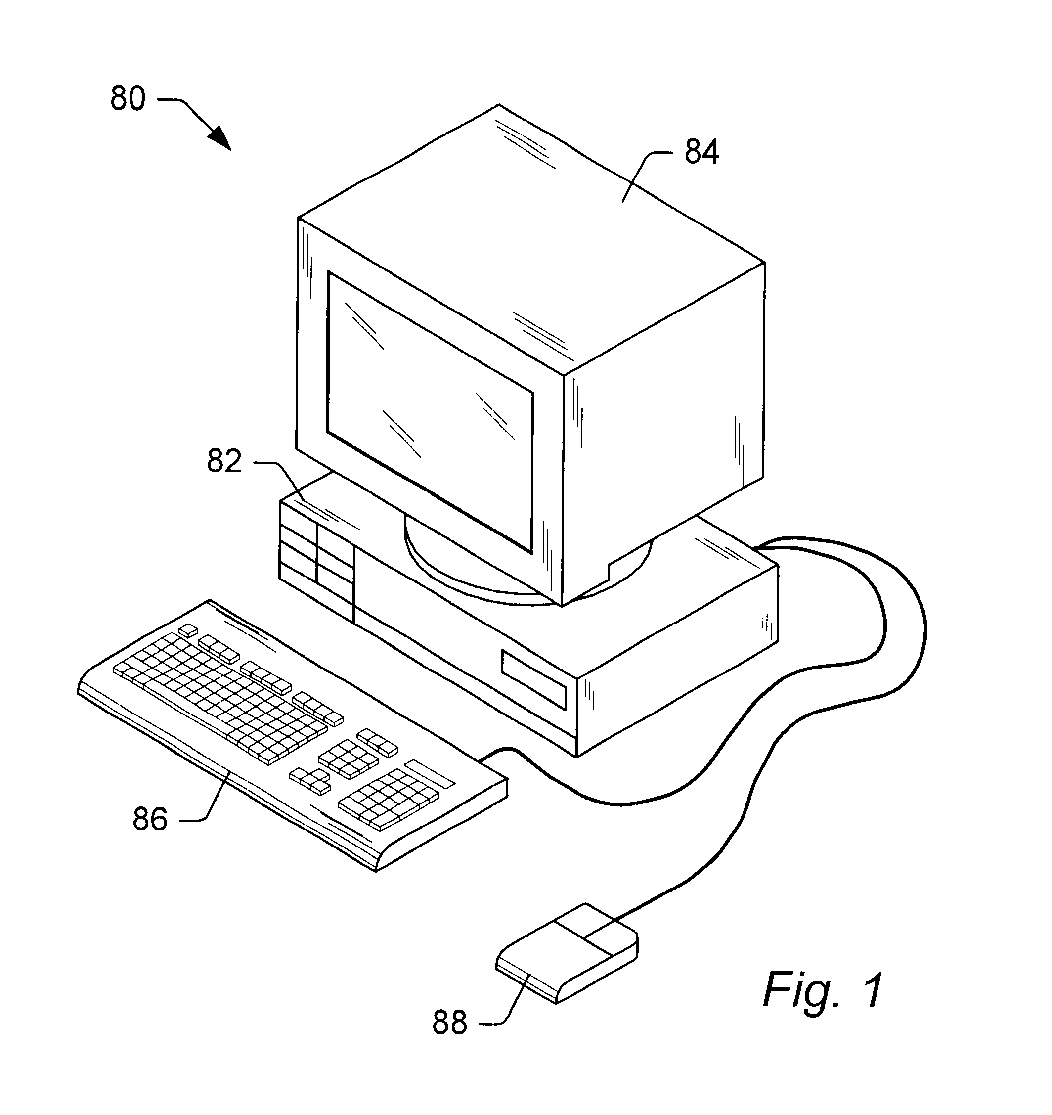
Computer System--FIG. 1

Referring now to FIG. 1, one embodiment of a computer system 80 that includes a three-dimensional (3-D) graphics system is shown. The 3-D graphics system may be comprised in any of various systems, including a computer system, network PC, Internet appliance, a television, including HDTV systems and interactive television systems, personal digital assistants (PDAs), and other devices which display 2D and or 3D graphics, among others.

As shown, the computer system 80 comprises a system unit 82 and a video monitor or display device 84 coupled to the system unit 82. The display device 84 may be any of various types of display monitors or devices (e.g...


PUM


Abstract

A computer graphics system that utilizes a super-sampled sample buffer and a sample-to-pixel calculation unit for refreshing the display, wherein the graphics system may store sample position information as offsets to coordinates in the sample buffer. The graphics system may have a graphics processor, a super-sampled sample buffer, and a sample-to-pixel calculation unit. The graphics processor renders samples into the sample buffer at computed positions or locations in the sample buffer. The sample positions may be computed using various sample positioning schemes. The sample-to-pixel calculation unit uses the position information to select the samples for filtering during generation of output pixels. In one embodiment, for each sample, the position information comprises one or more offset values, such as an x-offset and a y-offset, wherein the offset values are relative to pre-defined locations in the sample buffer, such as pre-determined pixel center coordinates or predetermined bin coordinates. The position information may be stored in the sample buffer with the samples, or may be stored in a separate sample position memory coupled to the graphics processor. The samples may also be stored according to a bin ordering, wherein the bin ordering indicates a position of the samples in the respective bin. The sample-to-pixel calculation unit may use the bin ordering of the samples in the bins to index into a look-up table memory to determine the position information of the samples. The graphics system may include double buffered sample position memories.

Description

1. Field of the InventionThis invention relates generally to the field of computer graphics and, more particularly, to high performance graphics systems.2. Description of the Related ArtA computer system typically relies upon its graphics system for producing visual output on the computer screen or display device. Early graphics systems were only responsible for taking what the processor produced as output and displaying it on the screen. In essence, they acted as simple translators or interfaces. Modem graphics systems, however, incorporate graphics processors with a great deal of processing power. They now act more like coprocessors rather than simple translators. This change is due to the recent increase in both the complexity and amount of data being sent to the display device. For example, modem computer displays have many more pixels, greater color depth, and are able to display more complex images with higher refresh rates than earlier models. Similarly, the images displayed ...

Claims


Application Information

Patent Timeline
Patent Type & Authority Patents(United States)
IPC IPC(8): G06T11/00G06T15/50G06T5/20G06T1/00G09G5/36
CPCG06T5/20G06T11/001G06T15/503G06T11/40
Inventor DEERING, MICHAEL F.
Owner ORACLE INT CORP
Learn More