Control system for movable heat recovery coils

a control system and heat recovery coil technology, applied in the direction of hot heat carrier steam generation, lighting and heating apparatus, instruments, etc., can solve the problems of increasing electricity consumption on abnormally hot days, reducing the efficiency of heat recovery coils, so as to improve heat recovery efficiency and reduce the effect of heat loss

Inactive Publication Date: 2002-11-26
IRISH FRANK E
View PDF19 Cites 9 Cited by
  • Summary
  • Abstract
  • Description
  • Claims
  • Application Information

AI Technical Summary

Benefits of technology

The present invention relates to a method and apparatus for selectively introducing one or more sets of heat transfer coils into the path of heated gasses to facilitate reclamation of at least some of the heat for transduction into useful energy. One form of the present invention is a set of coils adapted to circulate a heat-conducting fluid under pressure. The coils are in fluidic communication with a fluid chilling assembly. The coils are further adapted to be partially or completely introduced into an environment containing hot gasses (a hot zone), wherein heat is transferred from the hot gasses to the fluid circulating in the coils. The heated fluid is circulated into the chillers, where the heat is removed and transduced into a conveniently useful form of energy, such as electricity. The coils may b e only partially introduced into the hot gasses so as to optimize t he heat transfer to the coils and to prevent overheating of the heat conducting fluid and damage to the coils. The extent to which the coils are introduced into the hot gasses is variable and is a function of the temperature of the gasses and the fluid in the coils. In t he event of a power or control failure, the coils may be provided with a failsafe configuration to automatically remove them from t he hot gas environment.
One object of the present invention is to provide an improved heat energy reclamation system with an automatic failsafe to guard against accidental overheating.

Problems solved by technology

Business demand is high throughout daylight hours in the operation of stores and offices, but diminishes significantly thereafter.
For example, electricity usage soars on abnormally hot days due to widespread use of air conditioning equipment.
In reality, however, electric power demand is nowhere near constant.
The uneven demand for electric power requires that power generation capacity be sufficiently great to accommodate the maximum instantaneous demand.
This, in turn, leads to uneconomic operation of generally over-sized electric power generation facilities.
This exhausted heat is energy that is not being utilized by the system, thus drastically lowering the efficiency of the turbine 10.

Method used


Image

  • Control system for movable heat recovery coils
  • Control system for movable heat recovery coils
  • Control system for movable heat recovery coils

Examples


Embodiment Construction

For the purposes of promoting an understanding of the principles of the invention, reference will now be made to the embodiment illustrated in the drawings and specific language will be used to describe the same. It will nevertheless be understood that no limitation of the scope of the invention is thereby intended, and alterations and modifications in the illustrated device, and further applications of the principles of the invention as illustrated therein are herein contemplated as would normally occur to one skilled in the art to which the invention relates.

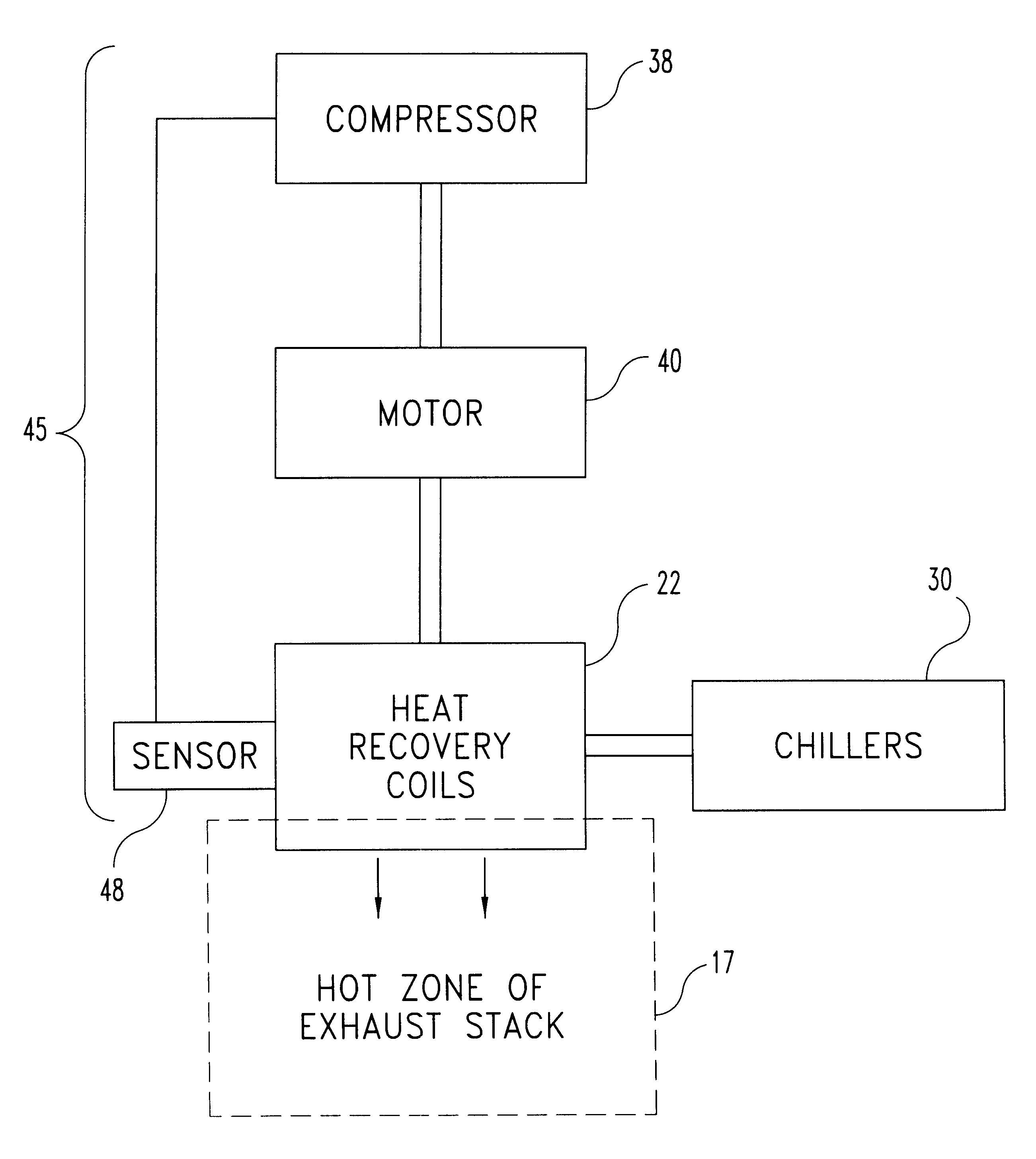
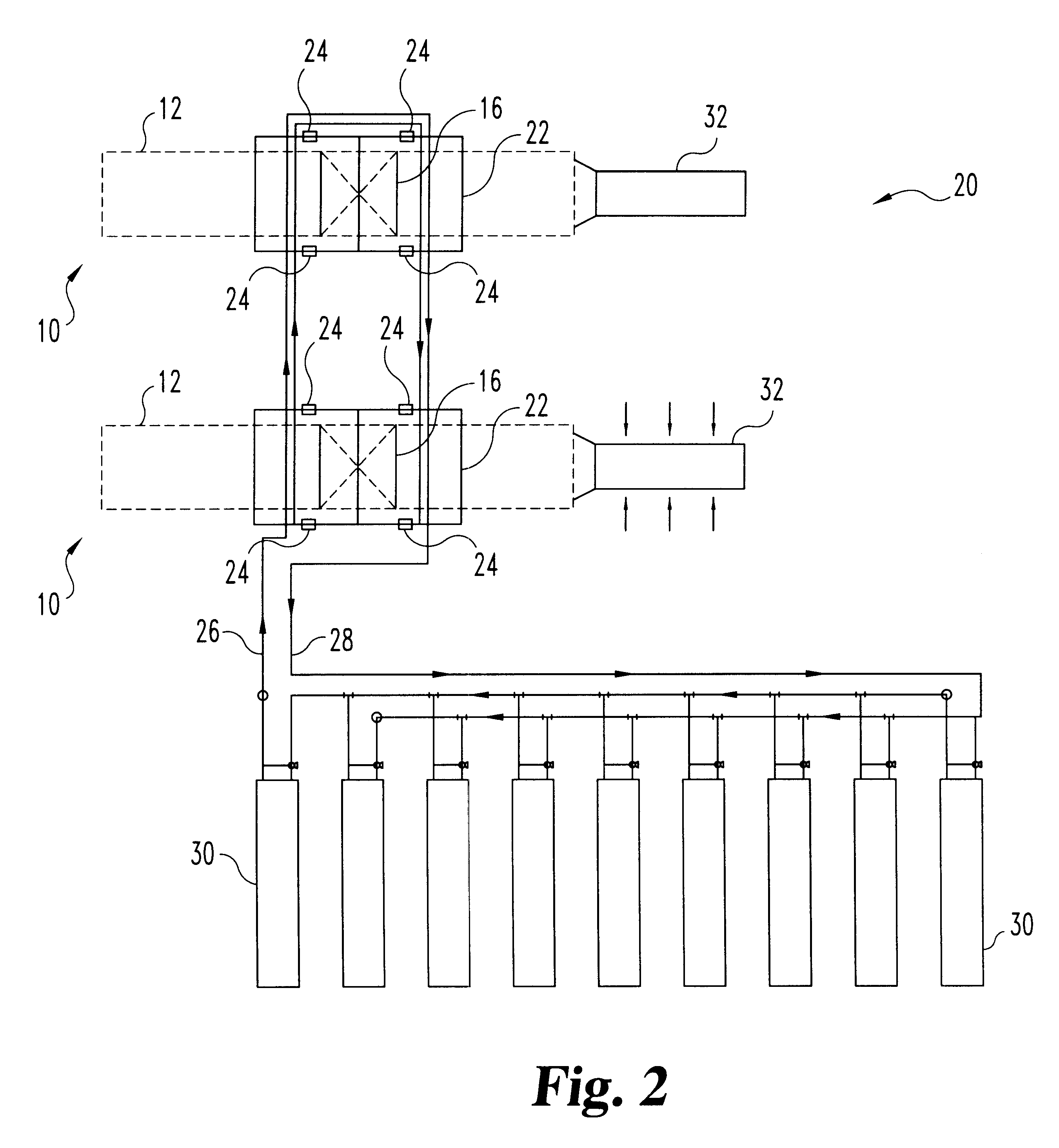
The use of a heat recovery system of the present invention with a pair of gas turbine electric generators 10 is illustrated schematically in FIGS. 2 and 7, and indicated generally at 20. The heat recovery system 20 is illustrated in use with two turbines 10, however it will be understood that the present invention may be used with any number of turbines 10. In fact, the heat recovery system of the present invention may be used...


PUM


Abstract

A method and apparatus for controlling heat recovery coils in an exhaust stack. A set of heat recovery coils at least partially filled with a heat conducting fluid is positioned in a hot zone. The recovery coils are biased in a direction out of the hot zone to prevent accidental overheating in the event of a control or power failure. A heat transduction system is connected in fluid communication with the heat recovery coils. Heat energy is transferred from the hot zone into the heat conducting fluid, and the heated heat conducting fluid is then flowed into the heat transduction system where heat is removed from the heat conducting fluid. The extracted heat is then transduced into useful energy.

Description

TECHNICAL FIELD OF THE INVENTIONThe present invention generally relates to heat recovery devices and, more particularly, to a control system for heat recovery coils.BACKGROUND OF THE INVENTIONAlthough electric power is utilized in diverse ways in the economy and demand remains high at all times, the demand for electric power nevertheless fluctuates markedly during the course of a day. Business demand is high throughout daylight hours in the operation of stores and offices, but diminishes significantly thereafter. Residential demand is highest in the evening hours. Industrial demand is relatively steady and high at all times. Other demands, such as for urban transportation, peak at differing times. Additionally, demand can vary greatly seasonally and with short-term changes in the weather. For example, electricity usage soars on abnormally hot days due to widespread use of air conditioning equipment.In an optimized power utilization system, all such demands would be complementary and...

Claims


Application Information

Patent Timeline
Patent Type & Authority Patents(United States)
IPC IPC(8): F22B1/18F22B1/00F28F27/00F28F9/007F28D21/00
CPCF22B1/1815F28D21/001F28F9/007F28F27/00F28F2280/10
Inventor IRISH, JOHN T.
Owner IRISH FRANK E
Why Eureka
Try Eureka