Oil recovery tool and system

a technology of oil recovery and oil, applied in the field of oil recovery tools and systems, can solve the problems of large quantities of crude oil remaining in the ground, marginal or economically unfeasible operation of wells, and often diminishing productivity

Active Publication Date: 2022-05-31
HYDROACOUSTICS INC
View PDF25 Cites 2 Cited by
  • Summary
  • Abstract
  • Description
  • Claims
  • Application Information

AI Technical Summary

Benefits of technology

[0003]After an oil well has been in operation for a time, its productivity often diminishes to a point at which the operation of the well is marginal or economically unfeasible. It is frequently the case, however, that substantial quantities of crude oil remain in the ground in the regions of these unproductive wells but cannot be liberated by conventional techniques. Often methods for efficiently increasing the productivity of a well are considered, provided they can be performed economically. Often a borehole can serve as an injection or monitor well and may allow for the insertion of a down hole seismic pressure wave generator.
[0008]The low-frequency vibration of reservoir rock formations is thought to facilitate enhanced oil recovery by (i) diminishing capillary forces, (ii) reducing the adhesion between rocks and fluids, and (iii) causing coalescence of oil droplets and enable them to flow within the water flood. Studies at the Los Alamos National Laboratory conducted by Peter Roberts have indicated that this process can increase oil recovery over substantially large areas of a reservoir at a significant lower cost than other enhanced oil recovery stimulation methods.
[0009]The systems and methods disclosed herein provide a low-cost tertiary solution to facilitate the reclamation of oil that had previously been uneconomical to retrieve. It is, therefore, a general object of the disclosed embodiments to enable the use of downhole vibratory seismic sources capable of generating elastic-wave vibration stimulation within a previously abandoned oil field in order to extract the immobile oil. By employing an apparatus for generating acoustic waves, further oil recovery is stimulated within an oil deposit in fluid contact with a borehole into which the acoustic wave source can be placed.
[0010]In accordance with the disclosed embodiments, disclosed is an electro-hydraulic seismic pressure wave source configured as an oil recovery tool. The operation of the disclosed oil recovery tool is facilitated by reducing the mechanical complexity of the tool while at the same time improving its overall reliability. The improvements include integration of a frameless motor into the tool, where the motor is specifically designed to operate in a water saturated environment. The rotor of the motor is directly attached to drive a rotating valve that is responsible for creating the seismic wave. The valve is designed with at least one and likely multiple ports for releasing the seismic energy. In one embodiment the oil recovery tool may include smaller ports along its length to implement a tapered hydraulic bearing. With a tapered bearing the valve uses pressurized water as the “bearing” material to reduce friction and may thereby eliminate the need for custom fabricated mechanical bearings. With the coupled rotor and valve, and tapered bearing, the tool is essentially reduced to a single moving (rotating) part. Additionally, the rotor is designed with a hollow shaft that, when attached to the valve, provides a direct path for pressurized supply water entering the tool to flow to the valve. This allows for greater fluid flow and reduction in possible cavitation (bubbles forming in the water). Additional water passages in and around the motor stator provide cooling to the motor during tool operation. Additionally, integration of the frameless, water-saturated motor; allows the tool to be reduced in diameter relative to prior down-hole tools, thereby allowing it to be employed in a larger range of well bore diameters starting at about 4 inches.
[0013]Also disclosed herein is a method for generating seismic pressure wave energy within an oil saturated strata, comprising: placing an acoustic wave generator in contact with a fluid within the strata; accumulating fluid pressure energy within the acoustic wave generator; and periodically releasing and transferring pressure energy with said generator to create wave energy that is transferred by the fluid into a porous medium of the strata, wherein releasing and transferring energy is accomplished by a frameless motor driving a rotary valve generator, said valve generator employing a hollow shaft for fluid passage, whereby the relative relationship of output ports on both a rotor and a stator within the fluid generator controls the release and transfer of a systematic pressure pulse to create the seismic pressure wave energy.

Problems solved by technology

After an oil well has been in operation for a time, its productivity often diminishes to a point at which the operation of the well is marginal or economically unfeasible.
It is frequently the case, however, that substantial quantities of crude oil remain in the ground in the regions of these unproductive wells but cannot be liberated by conventional techniques.
Nonetheless, large volumes of hydrocarbons remain in oil rich formations after secondary, or even tertiary recovery methods have been employed.
It is believed that a major factor causing the retention of the hydrocarbons in such formations is an inability to direct sufficient pressure forces on the hydrocarbon droplets residing in the pore spaces of the formations.
In the past it has not been cost effective to employ tertiary or enhanced oil recovery (also referred to as EOR) methods, even though up to seventy percent of the total volume of oil may still remain in an abandoned oil well after conventional oil recovery techniques are used.
The problem with ultrasonic waves is that in general, the depth of penetration or the distance that ultrasonic waves can move into a reservoir from a source is limited to no more than a few feet, whereas low frequency or acoustic waves can generally travel hundreds to thousands of feet through porous rock.
While sonic stimulation methods and apparatus to improve liquid hydrocarbon flow have achieved some success in stimulating or enhancing the production of liquid hydrocarbons from subterranean formations, the acoustic energy transducers used to date have generally lacked sufficient acoustic power to provide a significant pulsed wave.
The use of chemical surfactants and solvents, such as CO2, to reduce the surface tension and viscosity, while effective, are not widely used due to cost, contamination and environmental concerns.
However, seismic stimulation lacks any of the aforementioned limitations and continues to be explored as a viable enhanced oil recovery technique.

Method used


Image

  • Oil recovery tool and system
  • Oil recovery tool and system
  • Oil recovery tool and system

Examples


Embodiment Construction

[0027]Early oil recovery tool (ORT) embodiments employed pressurized fluid released in pulses as described herein. Such tools required complex mechanical components and internal fluid pathways, bearings with seals to provide fluid to the tool and to produce suitable seismic energy or waves. Earlier tools also required a separate pump(s) in order to gather and pressurize fluid.

[0028]Oil Recovery Tool

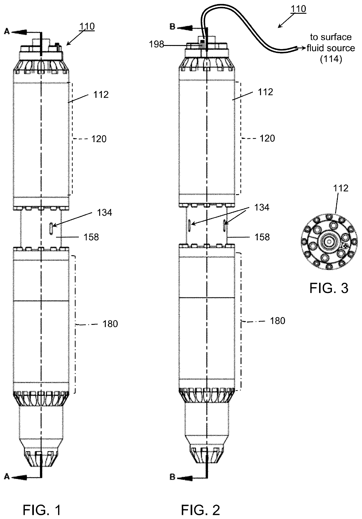
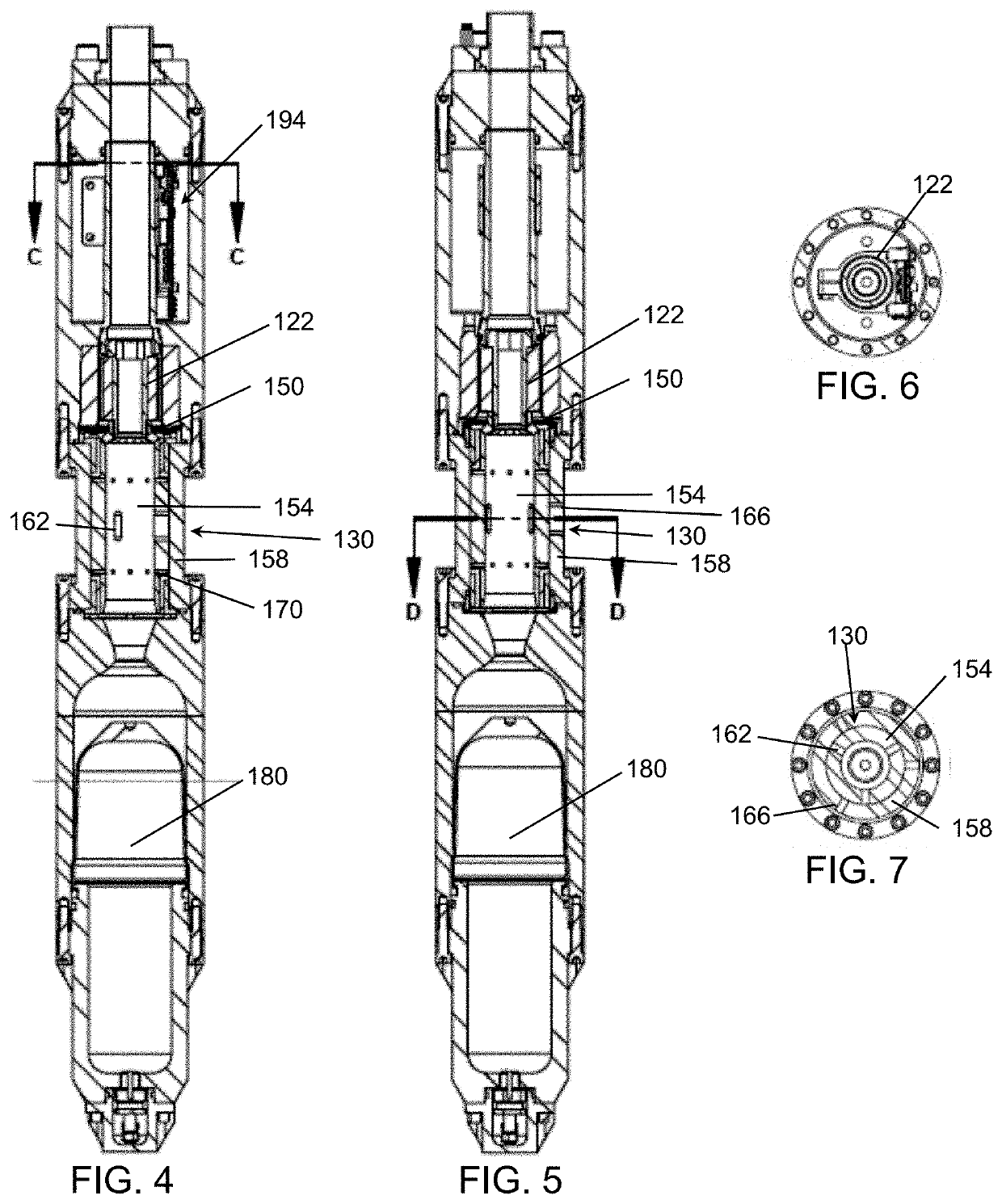
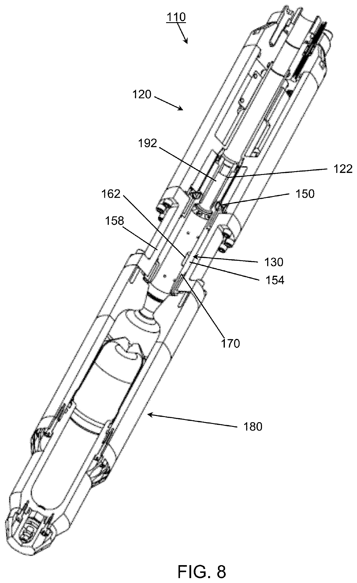
[0029]The oil recovery tool embodiments 110 described herein may be employed for imparting seismic wave energy (e.g., in the form of a wave) within an oil reservoir, so as to alter the capillary forces of residual oil. The tool comprises: a housing 112; a source of pressurized fluid 114 and electrical power. And, as described relative to FIGS. 1-13, the housing integrates a frameless, brushless motor, operatively located within the housing to receive the pressurized fluid and turn a rotor relative to a stator and align respective ports therein to generate the seismic waves.

[0030]In accord...


PUM


Abstract

An apparatus for generating acoustic waves within a medium to stimulate oil recovery within an oil reservoir. The apparatus is operable with a single moving part—a central rotor, and the rotor further includes a “conduit” through which the supply fluid passes.

Description

[0001]The present application is a continuation-in-part application of co-pending U.S. patent application Ser. No. 16 / 263,136 (now U.S. Pat. No. 10,704,938), filed Jan. 31, 2019, and claims priority, under 35 U.S.C. § 120, from U.S. patent application Ser. No. 16 / 263,136 (now U.S. Pat. No. 10,704,938), filed Jan. 31, 2019; this application also claims priority under 35 U.S.C. § 119(e) to U.S. Provisional Application No. 62 / 627,310 , filed Feb. 7, 2018, and U.S. Provisional Application No. 62 / 659,825 , filed Apr. 19, 2018; all of the above being hereby incorporated by reference in their entirety.[0002]The disclosed systems and methods are directed to generating acoustic waves. A downhole oil recovery tool provides a seismic source to enhance oil recovery. The systems and methods disclosed herein enhance oil recovery by means of vibratory stimulation, for example, to diminish capillary forces and encourage the rate of migration and coalescence of retained oil within the porous media o...

Claims


Application Information

Patent Timeline
Patent Type & Authority Patents(United States)
IPC IPC(8): E21B43/00E21B28/00E21B47/00H02K5/132H02K5/167H02K5/20E21B34/06
CPCE21B43/003E21B28/00E21B47/00H02K5/132H02K5/1672H02K5/20E21B34/06H02K5/203
Inventor VALTIERRA, ROBERT D.OZIMEK, MARK J.SISTO, EUGENE
Owner HYDROACOUSTICS INC
Why Eureka
Try Eureka