
Selective generation of multi-metallic sites on substrates and associated products

a multi-metallic site and substrate technology, applied in the direction of catalyst activation/preparation, natural mineral layered products, metal/metal-oxide/metal-hydroxide catalysts, etc., can solve the problems of limited catalyst loading and yield, high cost of current catalyst materials, and limited useful life, etc., to achieve the effect of increasing the control of cost and performance of the final produ

Inactive Publication Date: 2006-03-16
UNIV OF UTAH RES FOUND
View PDF13 Cites 2 Cited by
  • Summary
  • Abstract
  • Description
  • Claims
  • Application Information

AI Technical Summary

Benefits of technology

[0006] In one detailed aspect of the present invention, the substrate can be a highly porous material such as aerogel, xerogel, zeolite, silica, alumina, silica gel, or other similarly porous materials. Currently, aerogels are preferred for a wide variety of applications and can provide exceptionally high surface area, pore volume, and can facilitate reclamation of precious catalyst materials.
[0008] The targeting and optional oxidation or reduction steps using treatment with selected metal complexes can be repeated in order to achieve a desired loading of each co-catalyst metal and to control the ratio between co-catalysts. This can help to increase control of cost and performance of the final product.

Problems solved by technology

Unfortunately, many current catalyst materials are often expensive, have limited useful life, and / or have limited catalyst loading and yields.
Most often these methods produce randomly distributed metal oxides or metals and can suffer from non-selective deposition across the support surface.
This is especially problematic in multi-metallic catalysts where improved catalytic activity is the result of the combined synergistic effects of each of the constituent co-catalysts.
In such products, conventional random deposition techniques result in reduced catalytic activity than might theoretically be expected from the combination of certain co-catalysts.

Method used


Image

  • Selective generation of multi-metallic sites on substrates and associated products
  • Selective generation of multi-metallic sites on substrates and associated products
  • Selective generation of multi-metallic sites on substrates and associated products

Examples


examples

[0045] The following examples illustrate various methods of making aerogel supported multi-metallic catalysts in accordance with the present invention. However, it is to be understood that the following are only exemplary or illustrative of the application of the principles of the present invention. Numerous modifications and alternative compositions, methods, and systems can be devised by those skilled in the art without departing from the spirit and scope of the present invention. The appended claims are intended to cover such modifications and arrangements. Thus, while the present invention has been described above with particularity, the following Examples provide further detail in connection with several specific embodiments of the invention.

[0046] Preparation of Multi-Metallic Coated Substrates

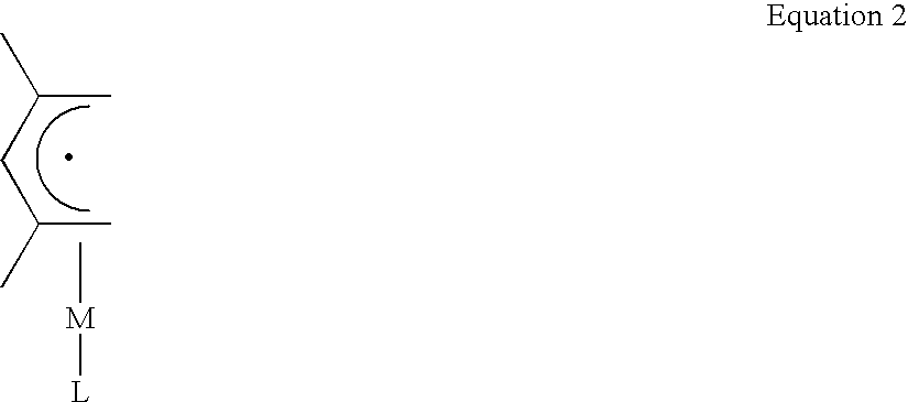
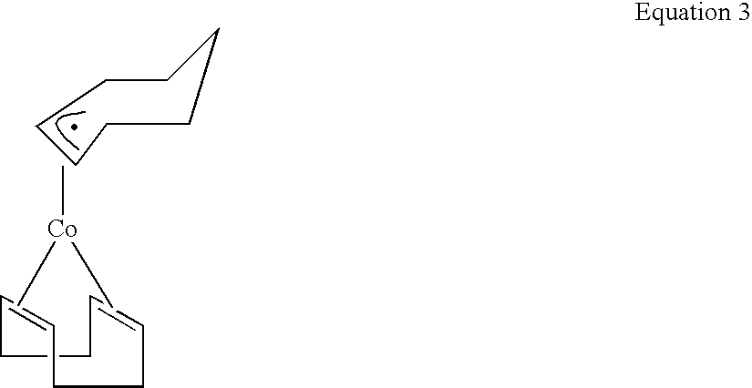
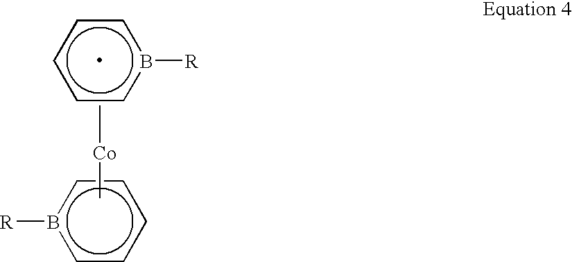
[0047] The following illustrates an exemplary embodiment of the present invention. Metallocenes, open metallocenes, and Fe(C5H5)(2,4-C7H11) were prepared by published procedures. See “...


PUM

PropertyMeasurementUnit
Metallic bondaaaaaaaaaa
Contentaaaaaaaaaa

Abstract

A method for forming multi-metallic sites on a substrate is disclosed and described. A substrate including active groups such as hydroxyl can be reacted with a pretarget metal complex. The target metal attached to the active group can then be reacted with a secondary metal complex such that an oxidation-reduction (redox) reaction occurs to form a multi-metallic species. The substrate can be a highly porous material such as aerogels, xerogels, zeolites, and similar materials. Additional metal complexes can be reacted to increase catalyst loading or control co-catalyst content. The resulting compounds can be oxidized to form oxides or reduced to form metals in the ground state which are suitable for practical use.

Description

RELATED APPLICATIONS [0001] The present application is a continuation-in-part of U.S. patent application Ser. No. 11 / 195,587, which was filed Aug. 1, 2005 and which claims the benefit of U.S. Provisional Application No. 60 / 592,631, filed on Jul. 30, 2004, each of which is incorporated herein by reference in their entirety.FIELD OF THE INVENTION [0002] The present invention relates generally to depositing materials on a surface. More particularly, the present invention relates to targeted deposition of metals on a substrate. Accordingly, the present invention involves the fields of chemistry, metallurgy, catalysis, and materials science. BACKGROUND OF THE INVENTION [0003] Deposition of various materials on surfaces can facilitate achievement of a wide variety of goals such as improving mechanical wear, corrosion resistance, chemical reactivity, catalytic value, and a number of other beneficial properties. More specifically, many metals and metal species can be used as catalytic agent...

Claims


Application Information

Patent Timeline
IPC IPC(8): B05D1/36B32B17/06B32B9/00B32B15/00C03C27/02
CPCB01J23/462Y10T428/12611B01J23/75B01J23/8913B01J31/1625B01J35/002B01J37/0203B01J37/0209C10G2/33C10G2/332C23C18/1639C23C18/1651Y10T428/12875Y10T428/1259Y10T428/12806B01J23/745B01J35/30
Inventor ERNST, RICHARD D.EYRING, EDWARD M.TURPIN, GREGORY C.DUNN, BRIAN C.
Owner UNIV OF UTAH RES FOUND
Learn More