Method and apparatus to achieve uniform ink temperatures in printheads

a technology of ink temperature and print head, applied in the field of printing systems, can solve the problems of large and higher velocity droplets, high power dissipation compared to aqueous inks, and non-uniform droplet output, so as to achieve uniform ink temperature, reduce temperature difference in ink distribution across the print head, and uniform droplet sizes and velocity

Inactive Publication Date: 2002-11-26
XEROX CORP
View PDF14 Cites 19 Cited by
  • Summary
  • Abstract
  • Description
  • Claims
  • Application Information

AI Technical Summary

Benefits of technology

In order to generate uniform droplet sizes and velocities from different droplet sources distributed across an AIP print head, a system to maintain the uniformity of ink temperature across the printhead is described. In one embodiment of the invention, a heat absorbing medium is placed on the opposite side of a substrate from the ink flowing across the printhead. The cooling effectiveness of the heat absorbing medium and the distance from the heat absorbing medium to the ink is adjusted to almost exactly compensate for the heating of the ink as it flows across the printhead such that the temperature difference in ink distributed across the print head is minimized. Alternative embodiments of the invention may adjust the flow of a cooling fluid across the backside of a printhead. As used in the following description, the backside of the printhead is a surface of the printhead upon which transducers are mounted. The heat characteristics and the flow of the cooling fluid are adjusted such that the ink temperature stays constant as the ink flows across the printhead.

Problems solved by technology

Uneven ink temperatures result in the output of nonuniform droplet sizes and velocities.
In particular, warmer ink at droplet sources near the ink outlet results in the output of larger and higher velocity droplets compared to droplets output by droplet sources located across the printhead near the ink source.
AIP printheads which are heated in order to eject phase change inks are particularly susceptible to these effects due the their relatively high viscosity (4-20 cp) resulting in high power dissipation compared to aqueous inks.
The nonuniform droplet sizes and velocities degrade image quality.

Method used


Image

  • Method and apparatus to achieve uniform ink temperatures in printheads
  • Method and apparatus to achieve uniform ink temperatures in printheads
  • Method and apparatus to achieve uniform ink temperatures in printheads

Examples


Embodiment Construction

.

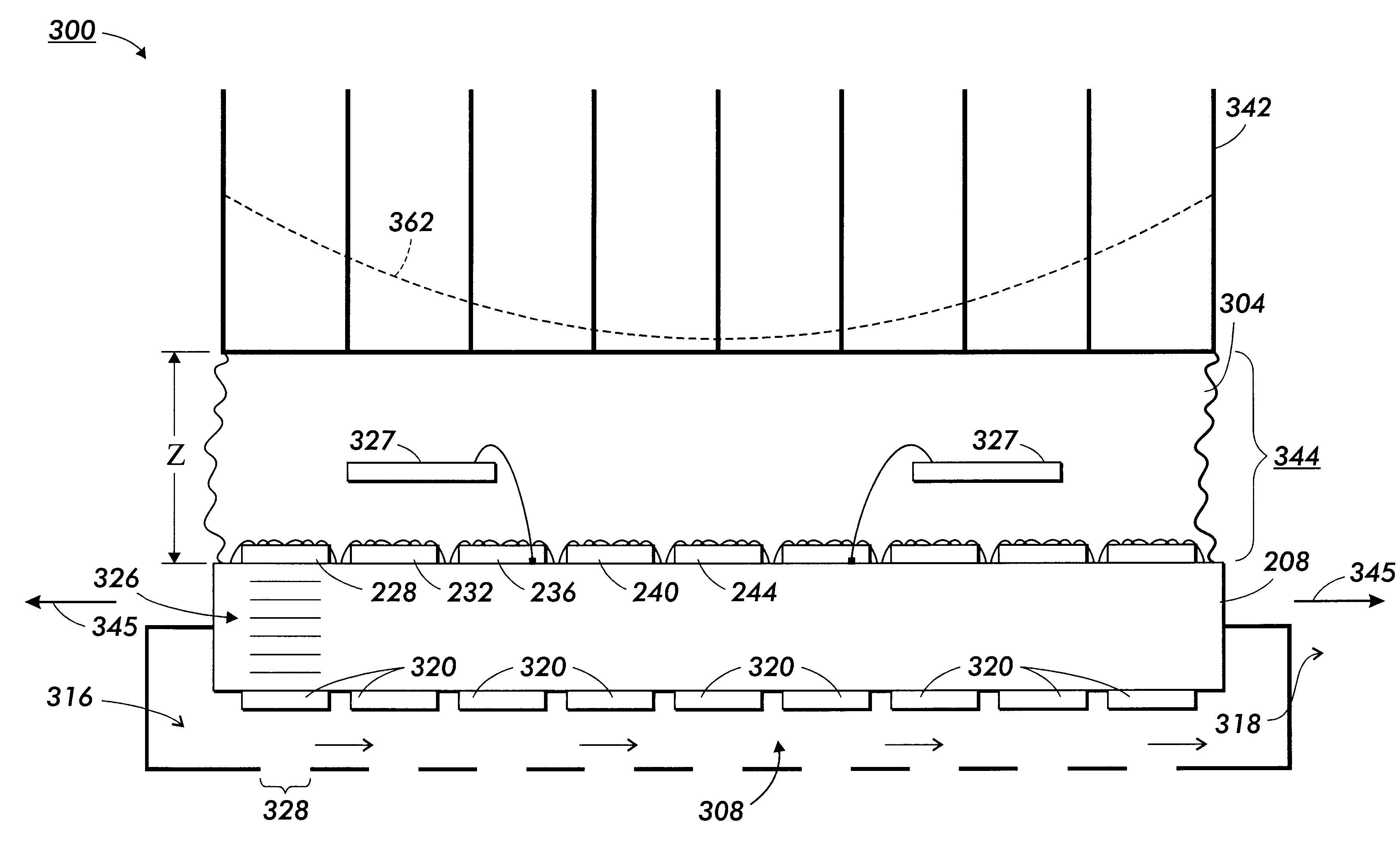
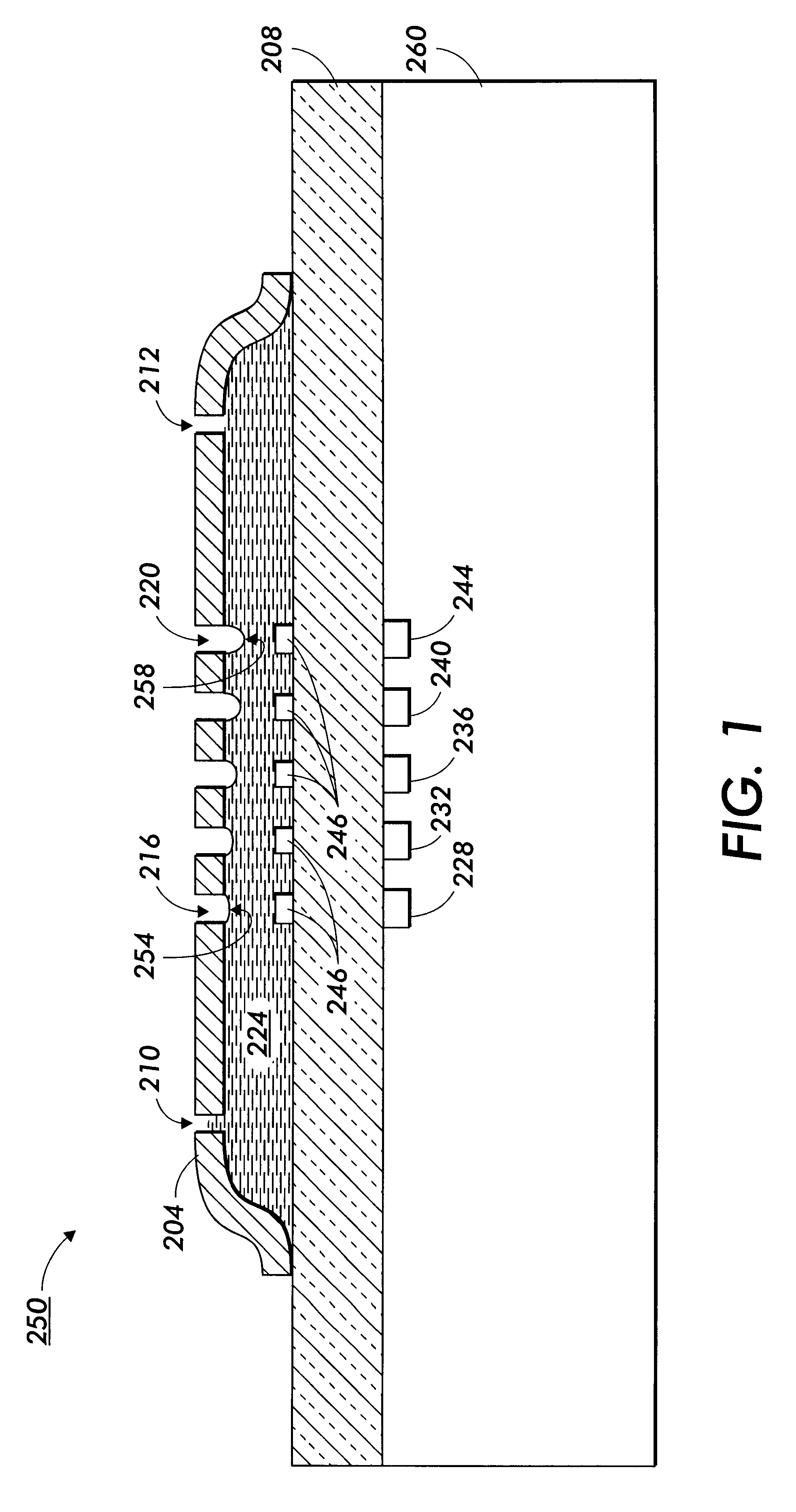
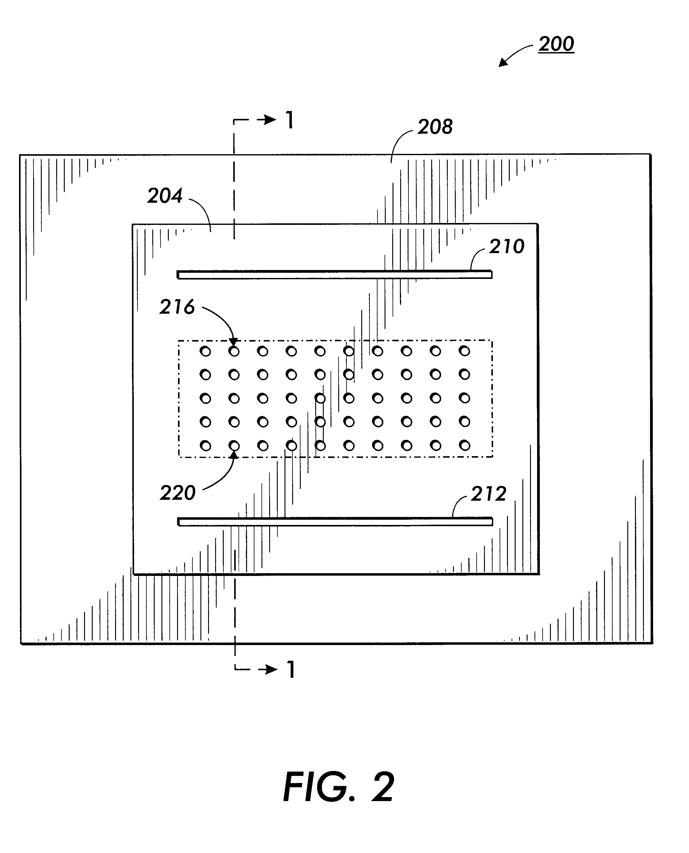
FIG. 1 illustrates an underside view 200 and FIG. 2 is a side view 250 of a printhead. In the embodiment illustrated in FIG. 1, a metal plate 204 is mounted over a glass layer 208. A first slot 210 serves as an ink source. Ink flows from first slot 210 to a second slot 212 that serves as an ink outlet. The flow of ink from first slot 210 to second slot 212 is maintained by a pressure differential between the two slots. The velocity of the ink flow from first slot 210 to the second slot 212 is determined by the distance between plate 204 and glass 208, the pressure differential along the ink flow, and also by the properties of ink 224 such as viscosity.

As ink 224 propagates from an ink source such as first slot 210 to an ink outlet such as second slot 212, the printhead structure and ink undergoes heating from acoustic energy and RF losses (hereinafter collectively referred to as heating). The heating occurs in the transducers 228,232,236, 240, 244 and also through acoustic dissipat...


PUM


Abstract

A system for improving the uniformity of ink droplets delivered from a plurality of droplet sources on a printhead is described. The system includes a cooling system that compensates for nonuniform heating effects in a printhead which results in nonuniform temperatures. The distribution of the cooling system, and the effectiveness of the cooling system is set to maintain an approximately uniform ink temperature across the printhead.

Description

FIELD OF THE INVENTIONThe present invention relates to printing systems. More specifically, the present invention relates to a method of using spatially controlled cooling profiles to maintain uniform temperature of ink across the active zone of an acoustic ink printhead.BACKGROUNDAs computing products continue to drop in price while increasing in power, printing technology is driven by the need to reduce prices while improving printer resolution. One technology under development is acoustic ink printing (AIP). AIP focuses acoustic energy to eject droplets of a fluid from a free surface onto a recording medium. The fluid is typically ink, although in specialized applications, the fluid may be a molten solder, a hot melt wax, a color filter material, a resist, and various other chemical and biological compounds.In AIP applications, a print head includes droplet sources that eject and deposit droplets on a receiving medium in a predetermined, controlled fashion. Each droplet sources i...

Claims


Application Information

Patent Timeline
Patent Type & Authority Patents(United States)
IPC IPC(8): B41J2/14B41J2/015
CPCB41J2/14008B41J2202/08
Inventor ELROD, SCOTT A.ROY, JOYSTEARNS, RICHARD G.FITCH, JOHN S.
Owner XEROX CORP
Why Eureka
Try Eureka