Air drag reducing apparatus

a technology of air drag and reducing apparatus, which is applied in the direction of vehicle body streamlining, monocoque construction, vehicle body, etc., can solve the problems of air drag, poor visibility, turbulence and drag,

Inactive Publication Date: 2002-11-26
TRANSTEX LLC
View PDF2 Cites 210 Cited by
  • Summary
  • Abstract
  • Description
  • Claims
  • Application Information

AI Technical Summary

Benefits of technology

More specifically, this is achieved by providing an apparatus which allows the panels to be moved outwardly from a drag reducing position to a position where the doors are in their fully retracted position adjacent their associated sides of the vehicle.
A further object of the present invention is to provide

Problems solved by technology

It is known that a significant amount of air drag results when a vehicle travels over a roadway; this is due to an area of low pressure created at the rear end of the vehicle.
For example, with a tractor-trailer type vehicle, the air makes a sharp bend around the squared-off back of the trailer, thus causing turbulence and drag.
Furthermore, the turbulence also causes poor visibility in rainy conditions and

Method used


Image

  • Air drag reducing apparatus
  • Air drag reducing apparatus
  • Air drag reducing apparatus

Examples


Embodiment Construction

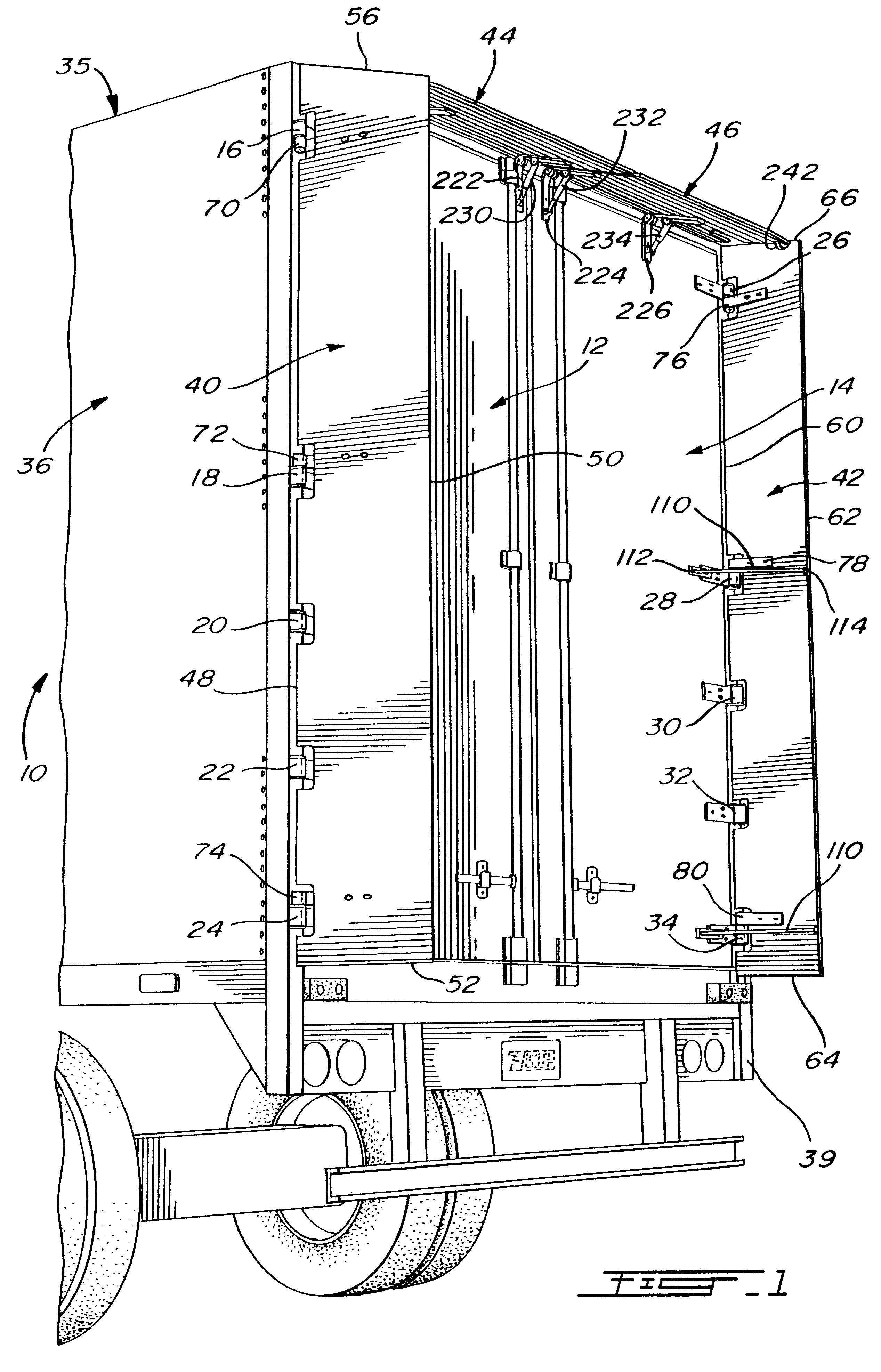
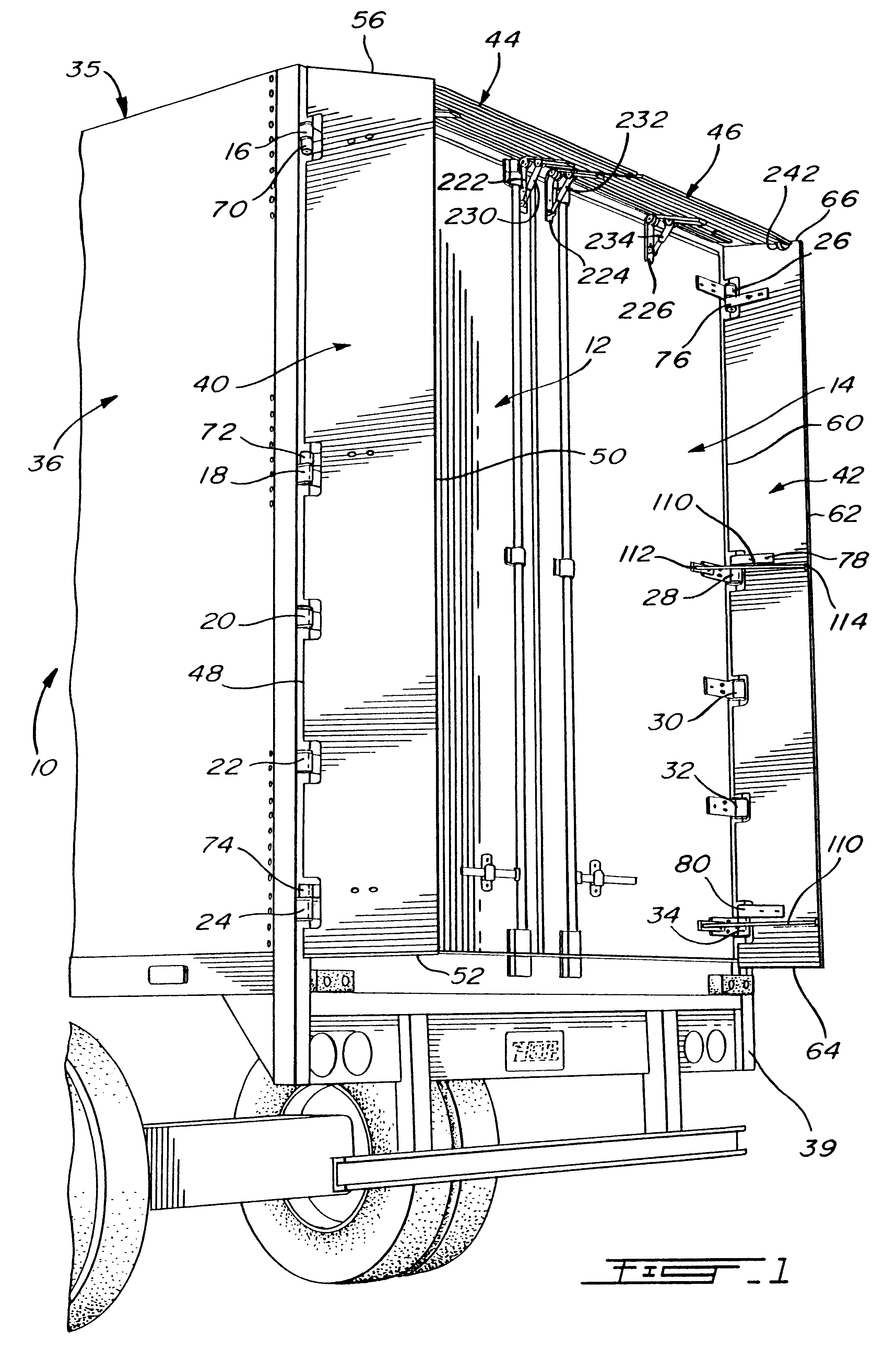
Referring to FIG. 1, there is shown the rear end of a vehicle 10, such as a truck or a trailer, which is closed by a pair of doors 12 and 14 of rectangular shape. The doors are respectively mounted by means of hinges 16, 18, 20, 22, 24 on one side and 26, 28, 30, 32 and 34 on the other side so as to move from their shown closed position to a fully retracted position where they are disposed parallel and adjacent to the opposite sides 36 and 38 of the vehicle.

The present invention is concerned with providing, at the rear of vehicle, an air drag reducing apparatus which in the present case includes a pair of side panels 40 and 42 and a pair of top panels 44 and 46. Panel 40 has a generally elongated rectangular shape with a leading edge 48 and a trailing edge 50 (defining the long sides of the rectangle) and a pair of opposite sides 52 and 56 (defining the short sides of the rectangle). Similarly, the side panel 42 has a leading edge 60 and a trailing edge 62 defining the long sides of...


PUM


Abstract

An air drag reducing apparatus for use with a vehicle having a rear end closed by a pair of doors consists of a rectangular shaped panel having a leading edge hingedly connected to the vehicle, the panel extending at about 16 degrees relative to the rearward projection of a side of the vehicle in a drag reducing position. As the door is opened, an element allows the panel to be moved between the door and the side of the vehicle to a position adjacent the side of the vehicle. As the door is moved back from the opened position to a closed position, the element causes the panel to return to its drag reducing position. The rear of a vehicle includes two side panels and two top panels.

Description

The present invention. relates to an air drag reducing apparatus for use with vehicles having a rectangular rear end closed by a pair of hingedly mounted doors.It is known that a significant amount of air drag results when a vehicle travels over a roadway; this is due to an area of low pressure created at the rear end of the vehicle. For example, with a tractor-trailer type vehicle, the air makes a sharp bend around the squared-off back of the trailer, thus causing turbulence and drag. To overcome this problem, engine power is required and therefore fuel. Furthermore, the turbulence also causes poor visibility in rainy conditions and an accumulation of dirt on the back of trailers.In the trucking industry, the aerodynamics of vehicles is a growing concern. Tests indicate that fuel savings from aerodynamic improvements are equivalent to fuel savings attained by a chassis weight reduction and require fewer services to maintain. The air resistance or aerodynamic drag of the vehicle inc...

Claims


Application Information

Patent Timeline
IPC IPC(8): B62D35/00
CPCB62D35/001
Inventor ROBERGE, KARICBOIVIN, MATHIEU
Owner TRANSTEX LLC
Why Eureka
Try Eureka