Telecommunication terminal and device for projecting received information

a technology of receiving information and telecommunication terminals, which is applied in the field of telecommunication terminals, can solve the problems of heavy and bulky handsets

Inactive Publication Date: 2002-11-26
ALCATEL LUCENT SAS
View PDF30 Cites 73 Cited by
  • Summary
  • Abstract
  • Description
  • Claims
  • Application Information

AI Technical Summary

Benefits of technology

The invention is based on the understanding that the telecommunication terminal described above can be improved by providing the terminal with projection means that comprise a circuit with an illuminatable and reflecting optical switching matrix and at least one optical lens for projecting the light reflected by the optical switching matrix onto the projection screen, which can only be used for the above-described device.
In addition, the invention is based on the concept that the above-described device can be improved by providing the device with an interface circuit adapted for connection to a telecommunication terminal.

Problems solved by technology

The miniature display is integrated into the handset rendering the handset rather heavy and bulky.

Method used


Image

  • Telecommunication terminal and device for projecting received information
  • Telecommunication terminal and device for projecting received information
  • Telecommunication terminal and device for projecting received information

Examples


Embodiment Construction

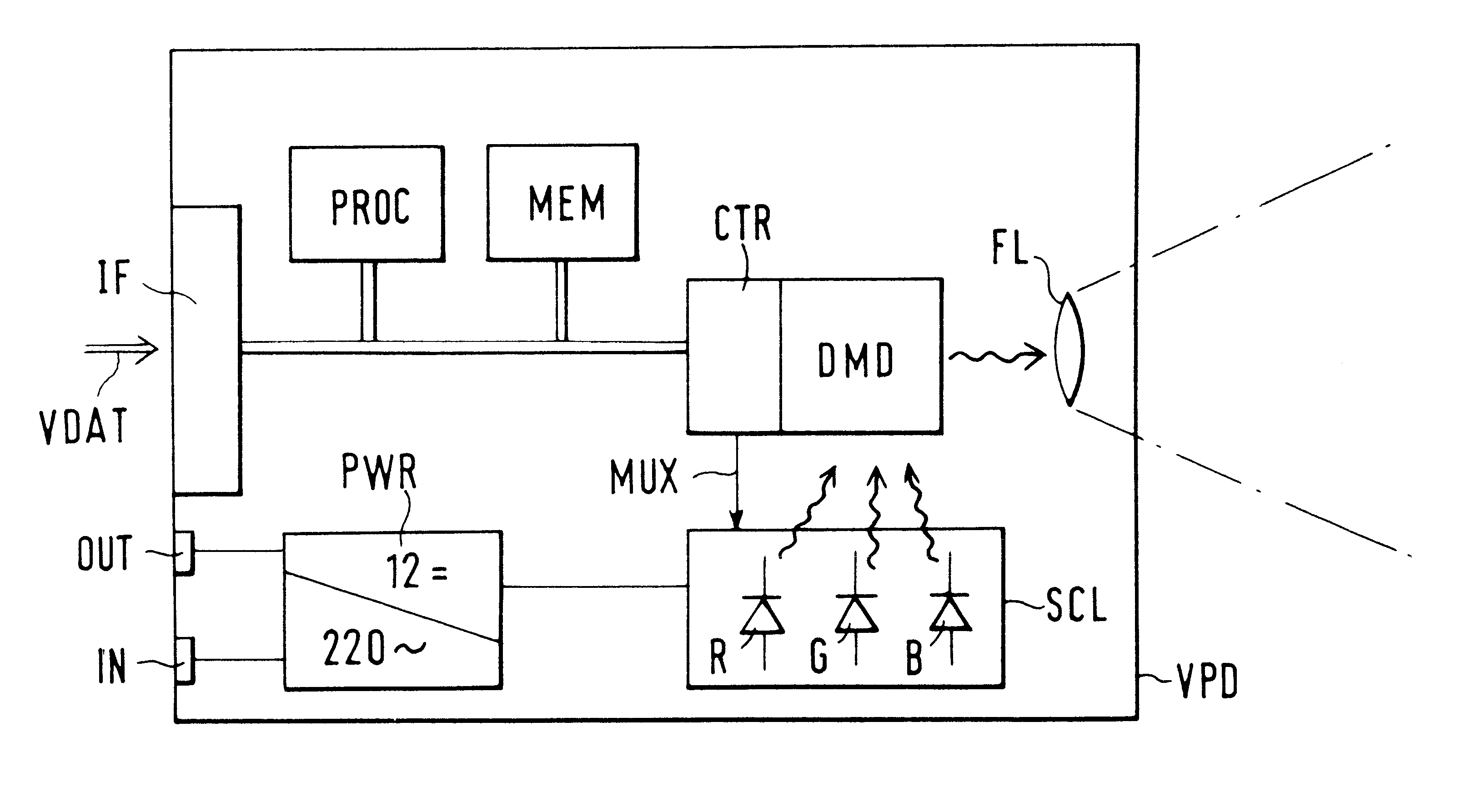
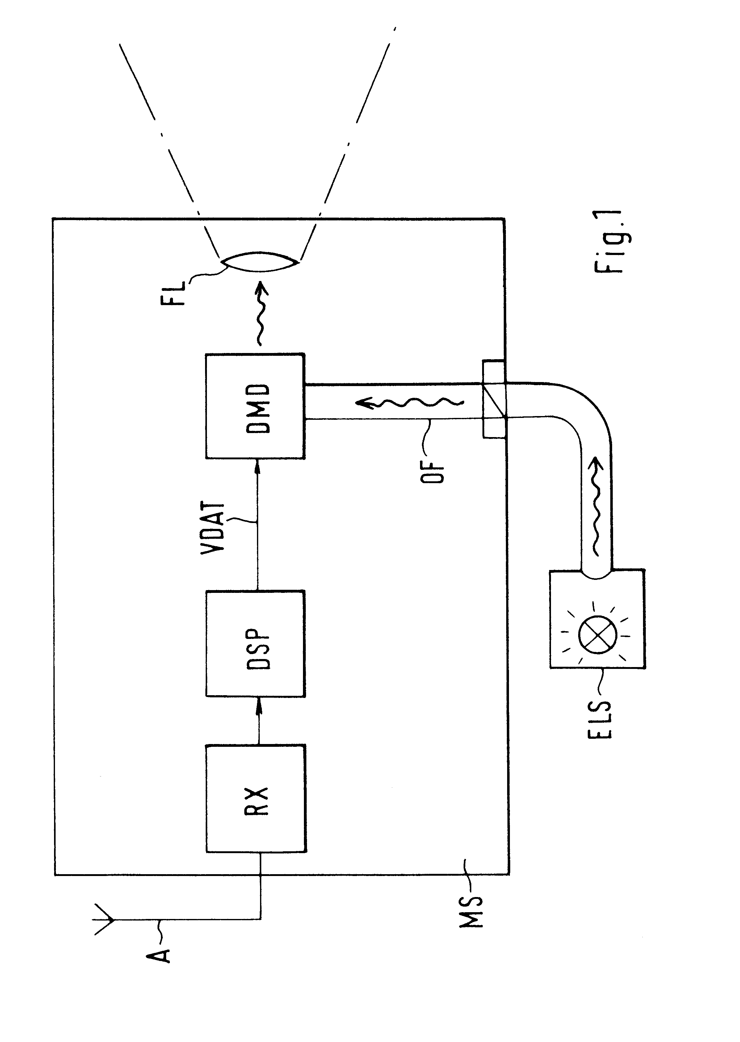
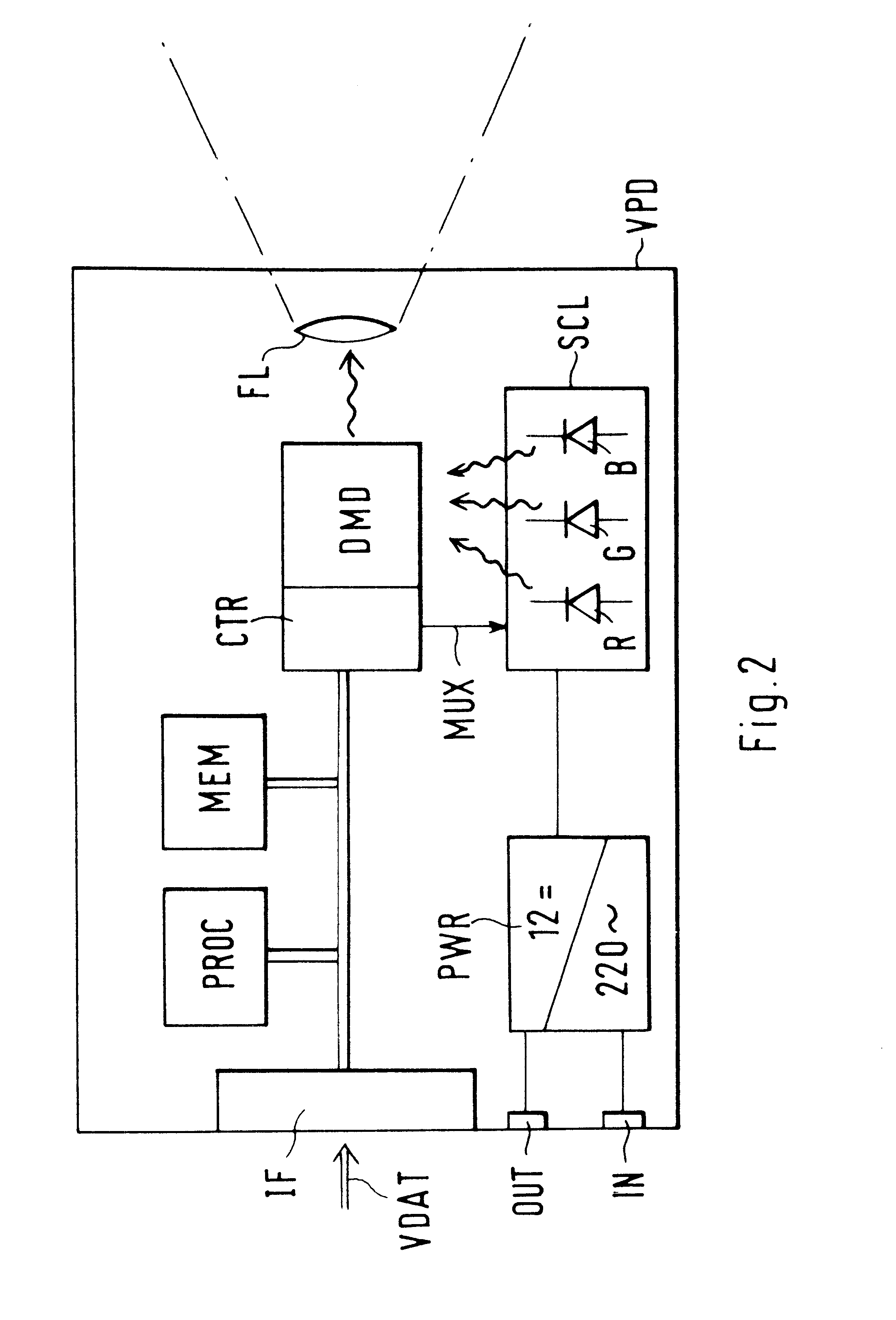
FIG. 1 shows a telecommunication terminal MS which in the present example is a radio telecommunication terminal according to the GSM standard. This radio telecommunication terminal MS, in the following shortened to "mobile device", comprises an antenna, to which a receiver RX, a digital signal processor DSP, and a circuit DMD are connected, in that order. In addition, the mobile device MS comprises an optical waveguide OF extending from a connection socket on the housing of the mobile device to the circuit DMD, and an optical lens FL.

The radio signals received via the antenna and the receiver RX are processed by the digital signal processor in the baseband. The received radio signals contain information VDAT to be represented visually with the help of the circuit DMD and the lens FL which are described hereinafter. In this example, the information VDAT corresponds to digital image data for controlling the circuit DMD which here is a so-called "digital mirror device". The circuit DMD...


PUM


Abstract

There is known a telecommunication terminal with a miniature display for received, visually perceptible information, such as, for example, fax messages. In addition, a device is known for projecting computer images or TV images, the device comprising a so-called DMD chip (Digital Mirror Device). It is proposed to improve the aforedescribed telecommunication terminal (MS) by providing the terminal with projection means (DMD, FL) which can basically only be used for the device described above. In addition, the device described above is improved by being provided with an interface circuit for connection to a telecommunication terminal. Accordingly, the conventional means known in the field of computer technology and TV technology for projecting images are now used in or for a telecommunication terminal, especially in a mobile radio telephone (MS). With the received image data, images can be projected directly onto a projection screen, for example, onto a wall. Several people can view the images simultaneously. An output device, such as, for example, a printer for fax messages, is not required.

Description

TECHNICAL FIELDThe invention relates to a telecommunication terminal for receiving visually perceptible information and for projecting the received information onto a projection screen. It is also directed to a device for projecting visually perceptible information onto a projection screen with an interface circuit for connection to another device receiving the visually perceptible information.BACKGROUND OF THE INVENTIONFrom EP 352914A2 there is known a telecommunication terminal with a means for receiving and for representing visually perceptible information. The telecommunication terminal described therein is a telephone with a miniature display for received information, for example, for received alphanumeric characters or for received fax messages. The miniature display used therein comprises an assembly of light emitting diodes (LEDs) which are viewed with a magnifying optical system, whereby the miniature display appears to the viewer like a large-area image display (virtual im...

Claims


Application Information

Patent Timeline
Patent Type & Authority Patents(United States)
IPC IPC(8): G02B1/00G02B26/08G09F9/37G09G3/34G09F9/00H04M11/06H04N7/14H04M11/02H04B1/06H04M1/00H04N9/31H04N1/00H04N5/74
CPCG02B1/00G02B26/08G09F9/00G09F9/37G09G3/34H04B1/06H04M1/00H04M11/02H04M11/06H04N1/00H04N5/74H04N7/14H04N9/31G02B26/0833H04M1/0272H04N9/3173G09G3/346G09G2370/18G09G5/026G09G3/001H04M11/066
Inventor KOPP, DIETERHORMANN, THOMAS
Owner ALCATEL LUCENT SAS
Why Eureka
Try Eureka