
Software development system that presents a logical view of project components, facilitates their selection, and signals missing links prior to compilation

a software development system and project component technology, applied in the direction of visual/graphical programming, program control, instruments, etc., can solve the problems of affecting the quality of the final product, so as to achieve the effect of quick and accurate recording

Inactive Publication Date: 2002-11-26
PHOENIX TECHNOLOGIES LTD
View PDF13 Cites 361 Cited by
  • Summary
  • Abstract
  • Description
  • Claims
  • Application Information

AI Technical Summary

Benefits of technology

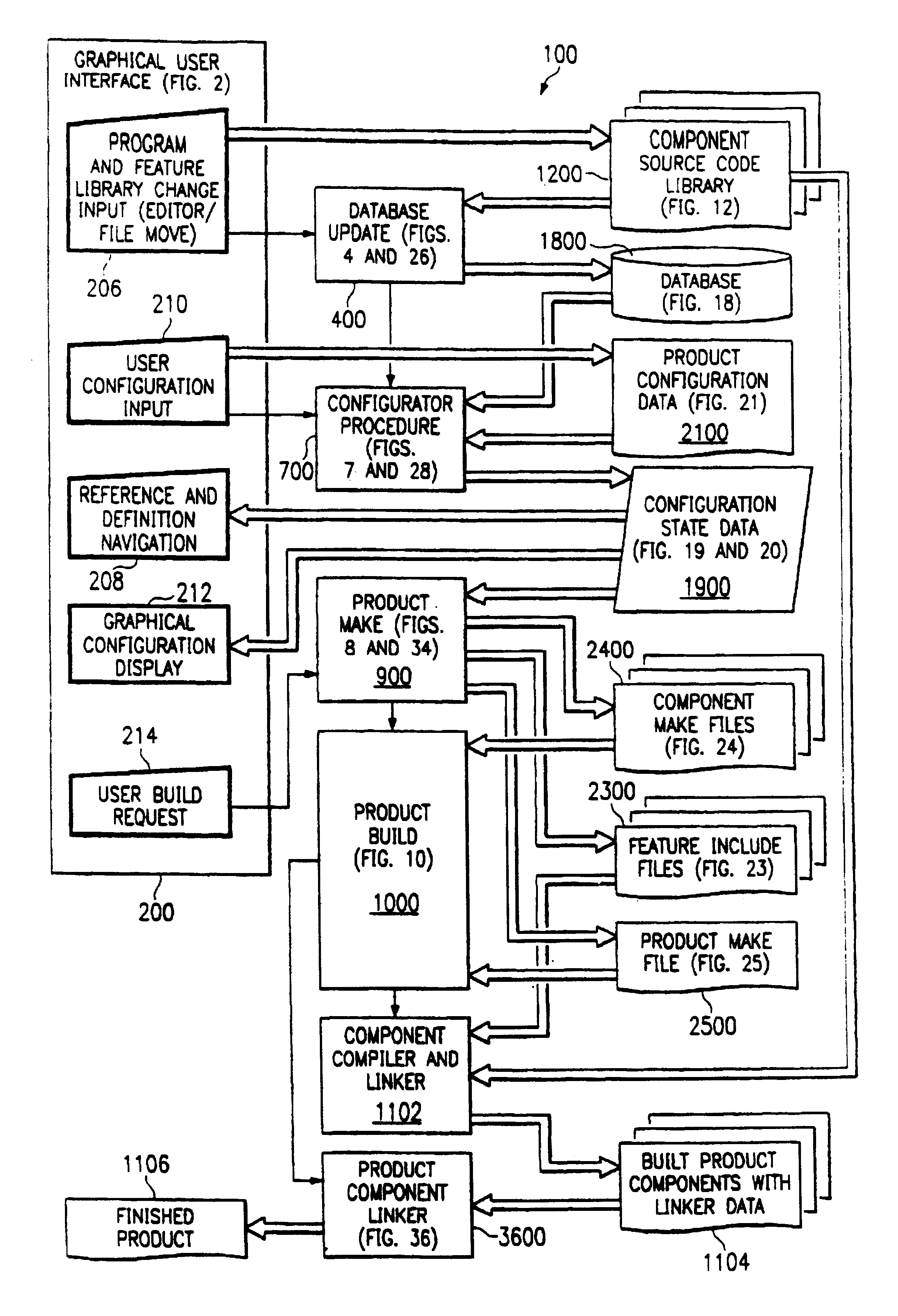
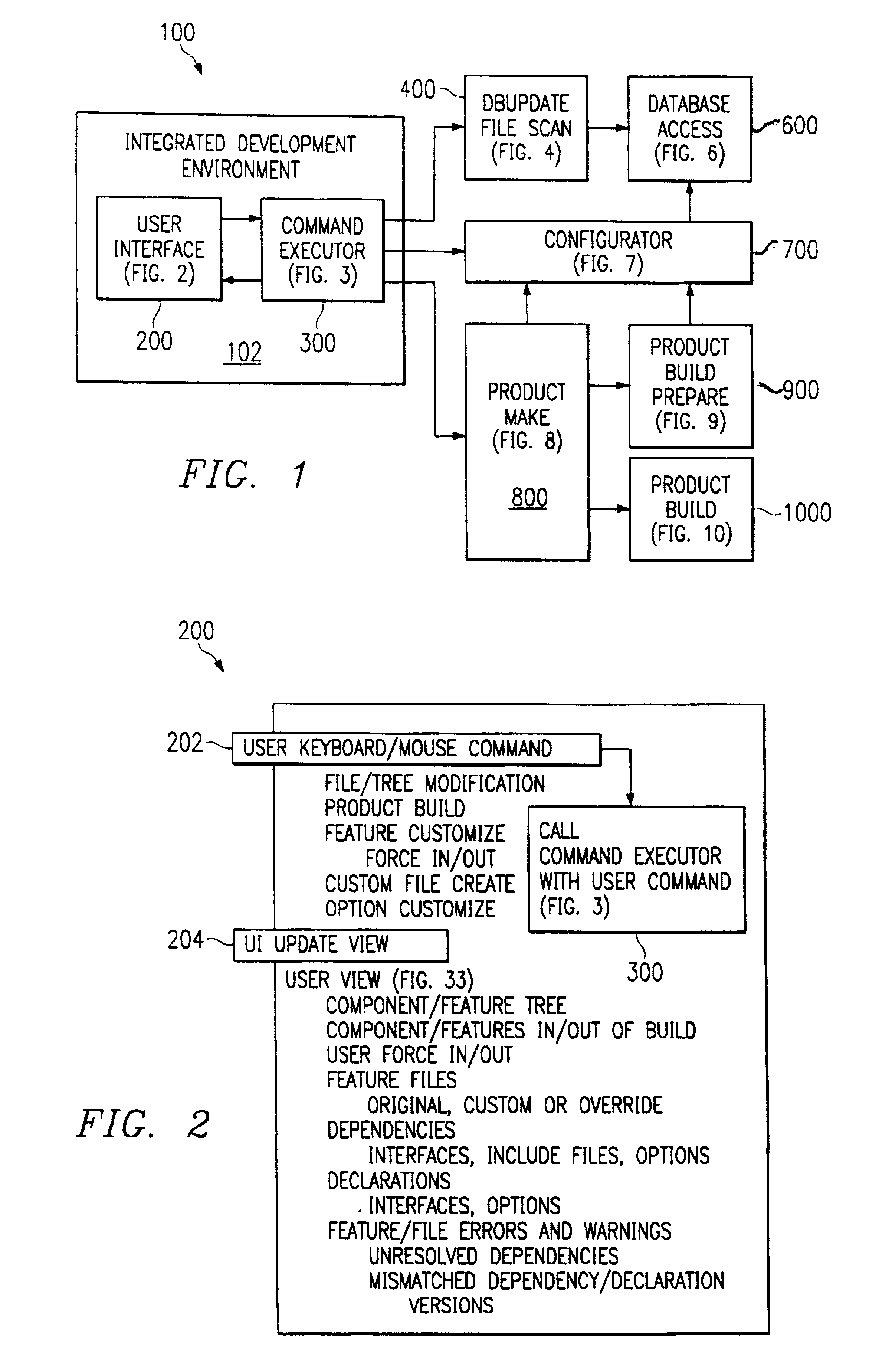
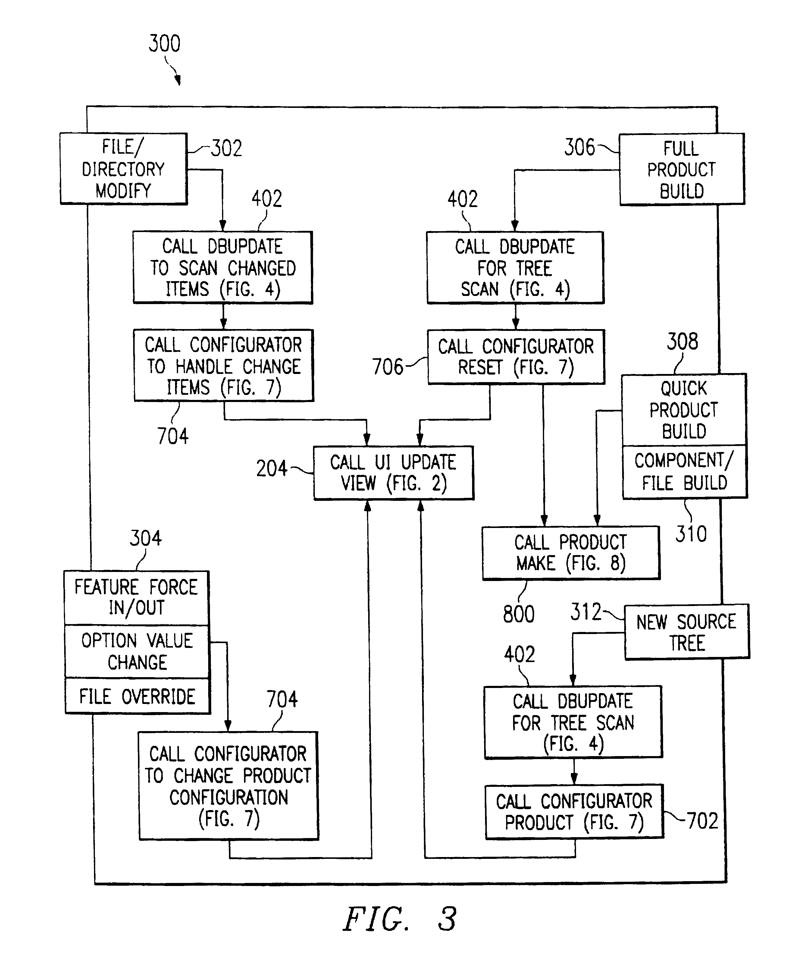
Next, a configurator routine 700 (FIG. 7), which maintains configuration status data 1900 (FIGS. 19 and 32) in RAM, is called upon at entry 704 to use the database 1800 to update the product configuration state data 1900 and to then configure 3000 (FIG. 30) the product to be built by redetermining which objects (components and features) to include, which to exclude, which objects to make designer options with what default values, depending upon which platform type (server, desktop, etc.) has been selected, what dependencies (options, calls to functions, file inclusions, etc.) need to be satisfied, and so on. Finally, at step 204 (in FIGS. 3, 5A, and 7), the routine UI UPDATE VIEW (FIG. 2) is called upon to regenerate the logical view of the software system within the left-hand window of FIG. 33A to share with the designer the new state of the system, and to permit the designer to change default object selections (see the menu 3334 in FIG. 33D) or to adjust the values of options (see the menu 3338 in FIG. 33E). In this quick and unobtrusive manner, all changes made by the designer are quickly and accurately recorded, the product to be built is reconfigured accordingly, and the designer is presented immediately with the results of all this activity.
If the designer does something, for example, that might cause the final linker in a conventional system to fail because of a dependency that could not be satisfied, such as by the absence within the library of any external procedure to which a "call" statement can be linked (this could, for example, be caused simply by the misspelling of a procedure's name), then, as is shown in FIG. 33B, little "X"s will appear beside the items that are causing the trouble. The designer may then, by simply clicking down through the displayed tree, quickly find, for example, the particular "dependency" that caused the problem (for example, the subroutine name "SendEOI" in the class "pic" shown as "pic.SendEOI" at 3324 in FIG. 33B). A "find" utility enables the file containing this reference to be quickly found, opened, corrected, and closed, with the system again being updated and corrected automatically to reflect the correction (the "X"s would then dissapear).
By way of brief explanation, to be supplemented below, the "feature.inc" files are placed into each feature subdirectory along with the source code files that actually define each feature. Each of the feature source code files contains the command "INCLUDE feature.inc". This causes the compiler or assembler to insert a feature's "feature.inc" file into all the source code files for the feature, where they may perform such tasks as changing class references to file path references, define options, and set switches that cause procedure calls to be deleted from the source code, if they call unselected components (see, for example, FIG. 23, where the value TRUE is assigned to "D_TIMER_DELAY" to cause a subroutine call to the "TIMER_DELAY" function to be included in the source code), or to be marked, for example, with a specific component name (to require the procedure linked to a call statement to reside within a feature of the named component). Likewise, a procedure entry point can be marked "override" to cause it to be selected in preference to an identical procedure name in some other source code file. Through the mechanism of the automatically-generated "feature.inc" files, all such user-option mechanisms can be adjusted by the system designer from the graphical user interface without the need to edit or alter the source code files themselves. This gives the system designer unprecedented control over the configuration of the finished product, with minimal effort.

Problems solved by technology

This ambiguity can cause further confusion at compile and link time.
Even then, improper linkages may result from identical names being used to mean different things in different sets of source files, from selection of the wrong set of two very similar sets of source files, or from version incompatibilities that compilers and assemblers cannot detect.
All of these problems, in combination, make software system development and integration more time consuming than ideally it should be.
However, new inputs may produce new outputs and different side effects.
For example, when a designer chooses to include modules into a software project build from 400 possible choices, it is difficult to know what "backward" referenced libraries may exist.
Second, the developer also gets immediate feedback of unresolved references prior to building the system.
This saves development time, because unresolved external references are normally reported only at the end of the build process when the link is done.
Any other combination of Usage fields for a single platform type, however, is not allowed and will cause a validation failure.
Otherwise, having more than one default resolution to a dependency will result in a validation failure.
Having more than one may result in multiple resolutions to a dependency causing a validation failure.

Method used


Image

  • Software development system that presents a logical view of project components, facilitates their selection, and signals missing links prior to compilation
  • Software development system that presents a logical view of project components, facilitates their selection, and signals missing links prior to compilation
  • Software development system that presents a logical view of project components, facilitates their selection, and signals missing links prior to compilation

Examples


Embodiment Construction

The Procedure and Label Declaration Macros consist of the PUBLIC_PROC, PRIVATE_PROC, END_PROC, PUBLIC_LABEL, PRIVATE_LABEL and FBM_LABEL.

The PUBLIC_PROC macro marks the start of a procedure that can be called from other components. It must be matched with an END_PROC macro. Its parameters are name, version and an optional INTERCEPT keyword. The name parameter is made up of a class name, zero or more subclass names and the actual procedure name, seperated by periods. The version parameter consists of major and minor version numbers seperated by a period. Callers with different major version number are incompatible. Callers with the same major version number but greater minor version numbers are incompatible. Increasing the minor version number implies backwards compatability. The optional INTERCEPT parameter indicates that the product component linker will fixup callers to call this procedure if there are multiple definitions.

The PRIVATE_PROC macro marks the start of a procedure that...


PUM


Abstract

A software development system develops a product from core library of source code elements, the core library being categorized into components having one or more features. A configurator develops configuration state data based on a designated platform type and the source code elements. A graphical user interface displays a visual and logical representation of the product according to the configuration state data, includine visual indications of any unresolved dependencies. A product make routine then generates the product from the source code elements according to the configuration state data.

Description

Not applicable.Not applicable.1. Field of the Invention / OverviewThe present invention relates generally to methods and systems for developing and integrating a software product by customizing and combining core components and integrating them to form the software product. More particularly and illustratively, the present invention relates to a software system for maintaining and re-using the core components of a Basic Input / Output System (BIOS) for a personal computer (PC) that simplifies BIOS deployment and that provides the architecture for an extensible yet maintainable core which enables rapid product development, enhancement, and modification.2. Background and State of the ArtA BIOS product is a piece of software code that executes when a PC is started up or "booted" and that is later called upon to provide various services while the PC is running. A development system for BIOS products must support all the peripherals that may be installed on any type of PC from a low-end basi...

Claims


Application Information

Patent Timeline
IPC IPC(8): G06F9/44
CPCG06F8/34G06F8/71
Inventor COHEN, FRANCESBOMBET, MARC ABRAHAMLUSINSKY, ROBERT DENNISLEWIS, TIMOTHY ANDREWSANDUSKY, MARC SHANE
Owner PHOENIX TECHNOLOGIES LTD
Learn More