Kinetic antifreeze device

a technology of antifreeze device and kinetic energy, which is applied in mechanical equipment, transportation and packaging, valve types, etc., can solve the problems of reduced air pressure, dry sprinkler system with sprinkler head, and lack of supervisory air within the network of pipes. , to achieve the effect of efficient and inexpensiv

Inactive Publication Date: 2002-12-10
CHRISTENSON JOEL P +1
View PDF32 Cites 31 Cited by
  • Summary
  • Abstract
  • Description
  • Claims
  • Application Information

AI Technical Summary

Benefits of technology

A primary object of the present invention is to prevent deluge, preaction, and dry pipe sprinkler systems from freezing by the provision of a bursting disc or a rupture disc on a dry sprinkler system. Another object of the invention is to provide an automatic drain for dry sprinkler systems which is efficient and inexpensive.

Problems solved by technology

A dry pipe system contains pipes which are charged with air under pressure and when the dry pipe system detects heat from a fire, the sprinkler heads open resulting in a decrease in air pressure.
A dry sprinkler system that has sprinkler heads which remain open, may not have supervisory air within the network of pipes.
Problems arise when water gets into what should be a dry sprinkler system and the ambient temperature drops below freezing.
Pipes and sprinkler heads sometimes become blocked with ice and or debris and render the dry sprinkler system useless.
That failure can be due to mechanical failure or chemical impurities.

Method used


Image

  • Kinetic antifreeze device
  • Kinetic antifreeze device
  • Kinetic antifreeze device

Examples


Embodiment Construction

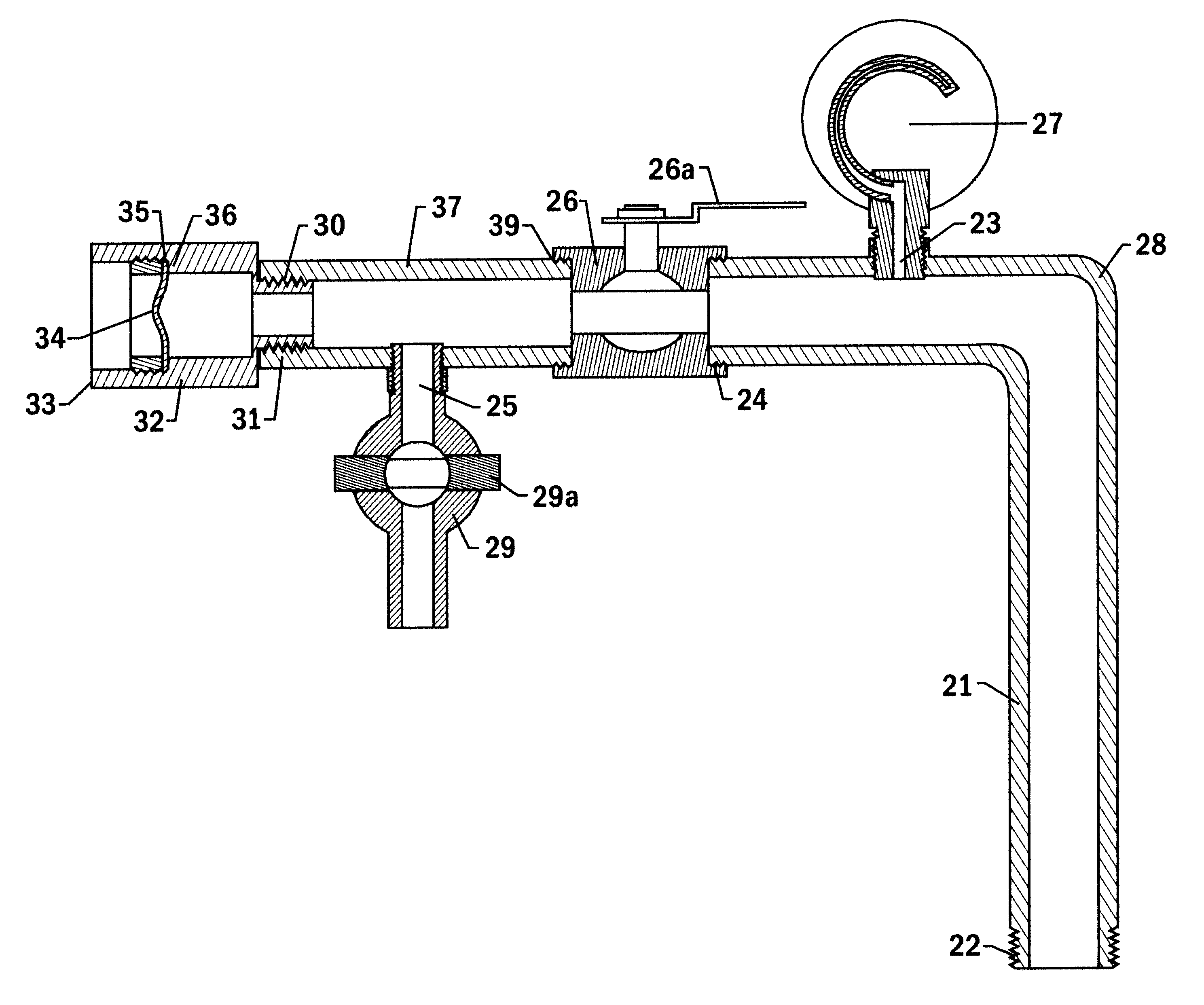
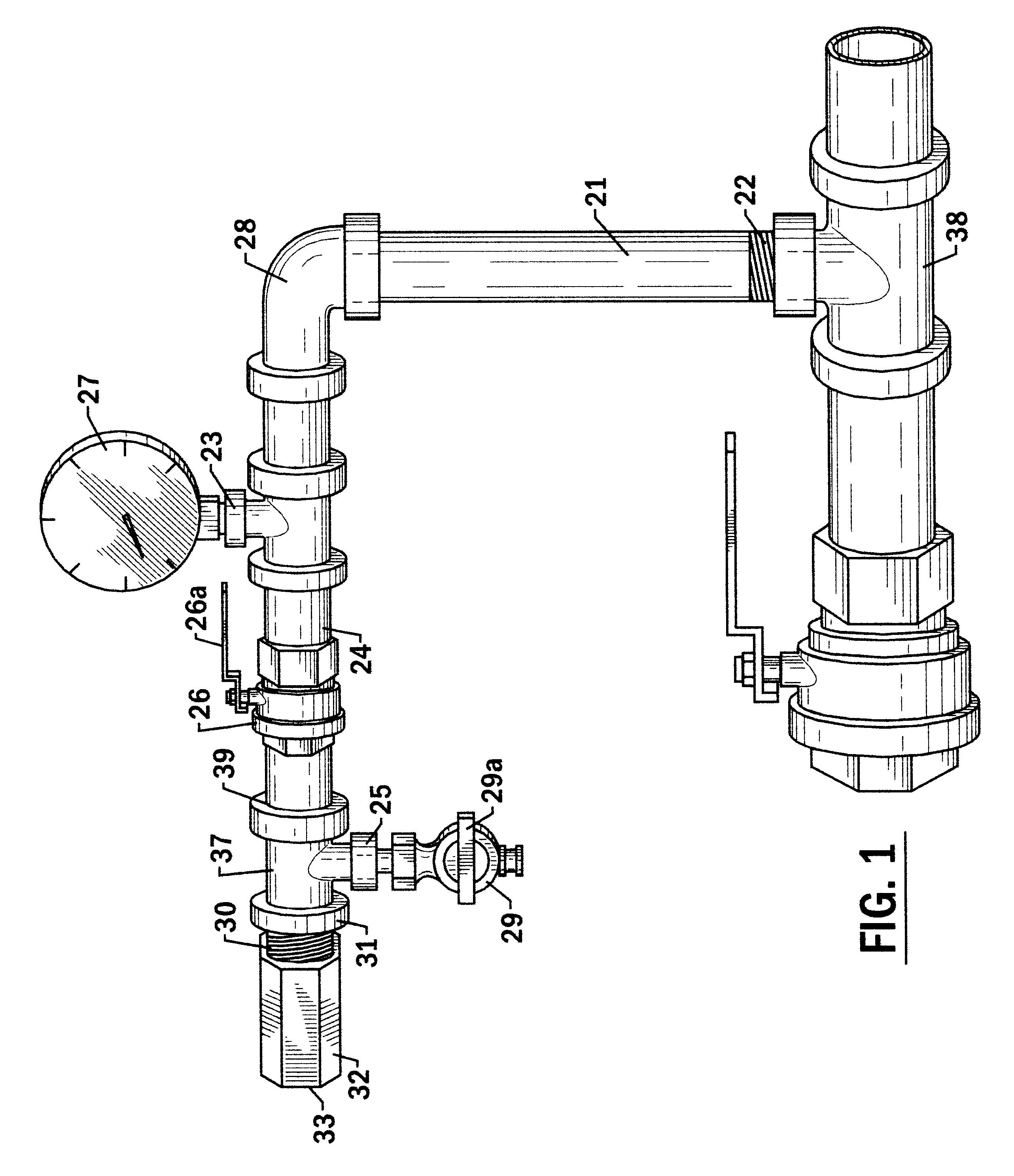
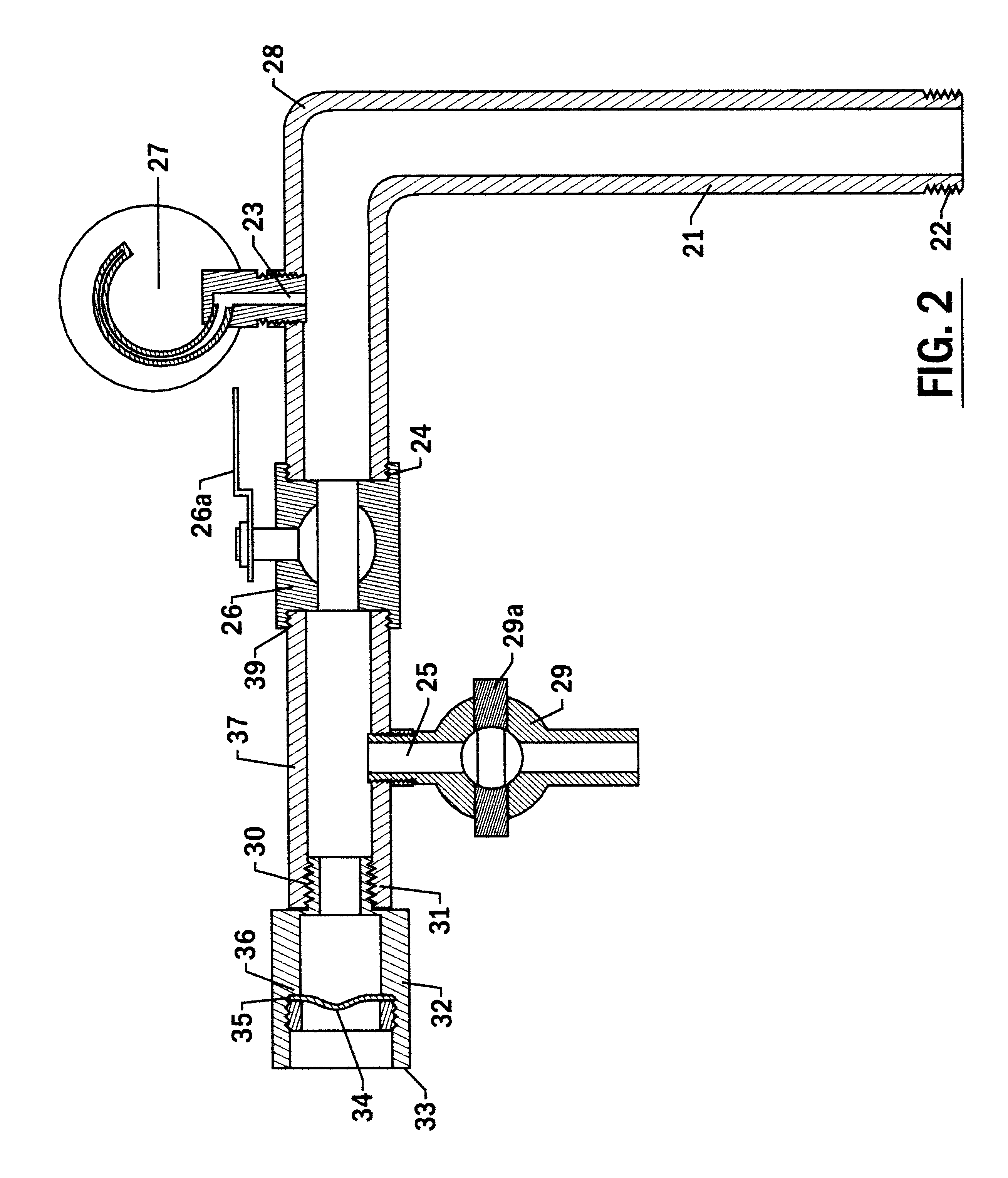
With particular reference to FIG. 1, is a first longitudinal pipe 21 which is attached to a position on a dry sprinkler system pipe 38 that is adjacent to a drain valve. The dry sprinkler system could be a preaction, deluge, or dry pipe sprinkler system. These three dry sprinkler system pipes may contain supervisory air which is air charged under pressure. These three dry sprinkler system pipes may also contain air at atmospheric pressure.

The first longitudinal pipe 21 has a first pipe thread 22 at the point at which the invention meets the dry sprinkler system pipe 38. The first longitudinal pipe 21 has a port 23 for attachment of a pressure gauge 27. An isolation valve 26 which is a ball valve with a valve handle 26a is connected to the second end 24 of the first longitudinal pipe. The position of the ball valve handle 26a shows that when the ball valve handle 26a is parallel with the second end 24, that the valve is open and allows flow of air, water, and fire suppression fluid. ...


PUM


Abstract

A kinetic antifreeze device for preventing a dry sprinkler system from freezing is disclosed. The kinetic antifreeze device contains a longitudinal pipe for guiding air and water flow connected to a dry sprinkler system pipe at a junction adjacent to a drain valve. The longitudinal pipe provides a pressure gauge, an isolation valve, a bleed off valve and a relief disc for providing over pressure relief. The relief disc is either a bursting disc device or a rupture disc device which remains closed when the dry sprinkler system is contains only air. The relief disc exits or opens upon fire suppression fluid entering the system after a main supply of fire suppression fluid is actuated by the dry sprinkler system and the pressure increases due to the presence of fire suppression fluid in the dry sprinkler system.

Description

1. Field of the InventionThis invention relates to dry sprinkler fire suppression systems and particularly to a new use of a bursting disc device or rupture disc device attached to a dry sprinkler system pipe to prevent dry sprinkler systems from freezing and to the new use of a bursting disc device or rupture disc device as an automatic drain for dry sprinkler systems.2. Description of the Related Art Including Information Disclosed Under 37 CFR 1.97 and 1.98Dry sprinkler systems utilize piping networks which are typically anhydrous, dry, or free of water until activated by heat from a fire. The main reason for keeping the piping networks dry is to prevent them from freezing when the temperature drops below 0.degree. C. This is in contrast to wet pipe systems wherein the pipes contain water at all times.Three types of dry sprinkler systems include dry pipe, preaction, and deluge systems. Dry sprinkler system pipes which contain air charged under pressure are sometimes referred to a...

Claims


Application Information

Patent Timeline
Patent Type & Authority Patents(United States)
IPC IPC(8): A62C35/62A62C35/58F16K17/02F16K17/16
CPCA62C3/004A62C35/62F16K17/16Y10T137/1692Y10T137/1714
Inventor CHRISTENSON, JOEL P.ENGEL, GARY M.
Owner CHRISTENSON JOEL P
Why Eureka
Try Eureka