

Flat surface-mounted multi-purpose wire
a multi-purpose, flat wire technology, applied in the direction of cable, laminated bus-bars, coupling device connections, etc., can solve the problems of cumbersome removal methods, long telephone and antenna/catv cords, and long extension cords, and the choice of adding, changing or moving any of the many wiring applications in the existing commercial or residential application is expensive or obtrusive or both, and the user can not easily adjust the placement of the wir
- Summary
- Abstract
- Description
- Claims
- Application Information
AI Technical Summary
Problems solved by technology
Method used
Image

Examples
embodiments
Wire Embodiments
Alternating Current (AC) Electrical Wire
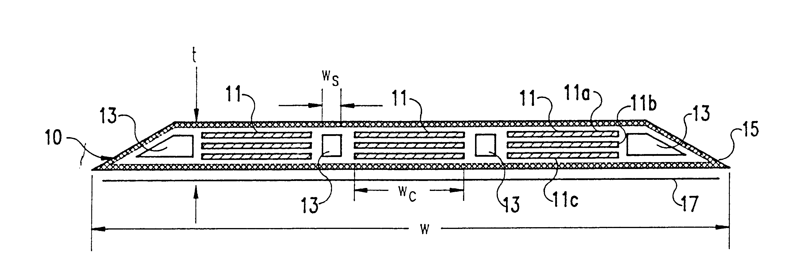
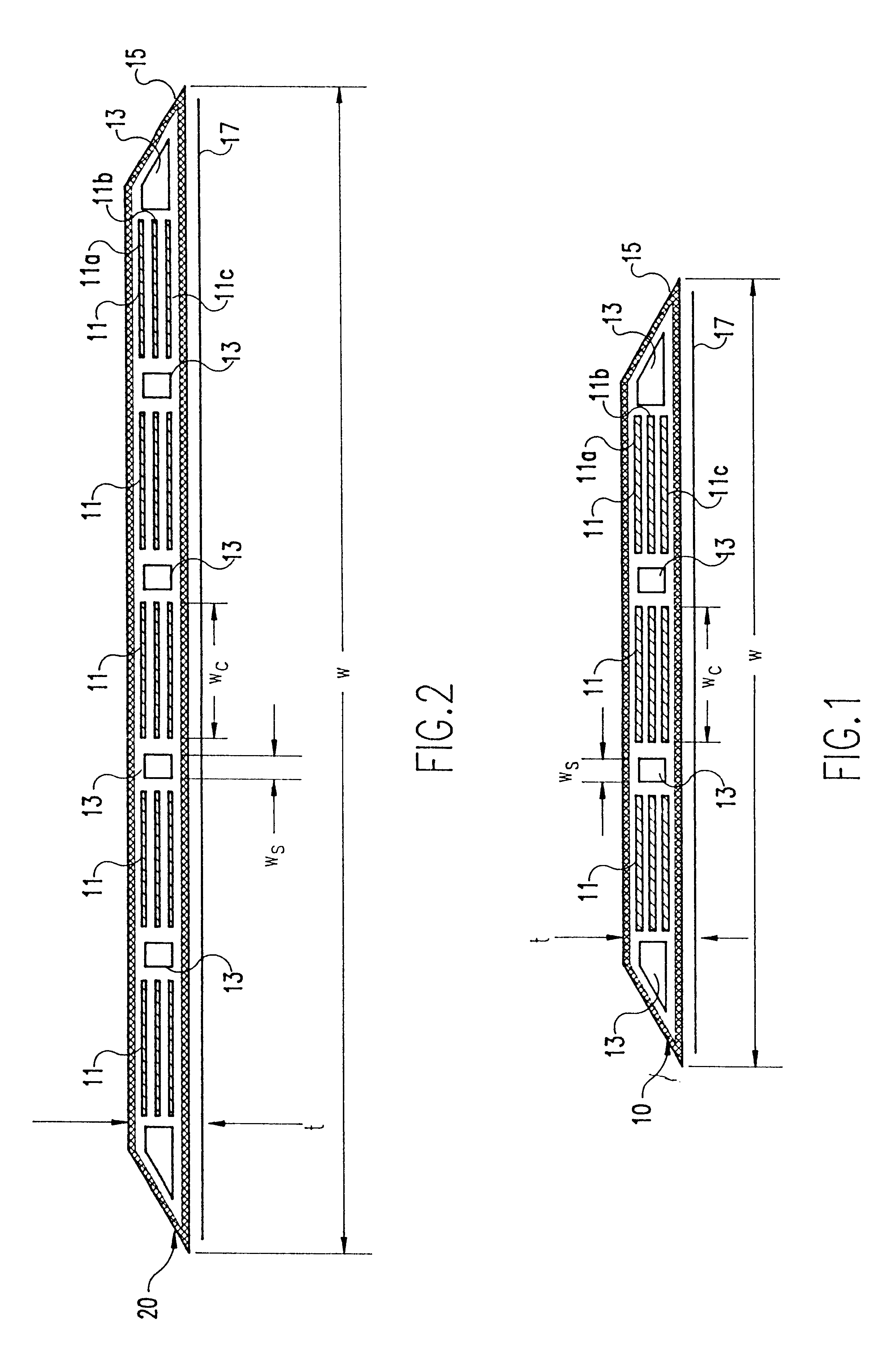
Referring now to the drawings, and more particularly to FIG. 1, there is shown an exploded side cross-sectional view of a standard 110 VAC 3-conductor wire embodiment in accordance with the present invention. The exploded cross-sectional view is for illustrative and discussion purposes only. In the actual 3-conductor embodiment, there would be no visible spacings (i.e., the white areas in FIG. 1) between the conductors, insulation, and adhesives components, each of which is described further below.
Generally, the electrical wire 10 is a flat, flexible, wire that allows the user to bring electricity to any area of a wall or ceiling in a room. The electrical wire 10 is mounted to the surface of the wall or ceiling, thereby eliminating the need for costly inner wall or ceiling rewiring. The wire may be painted or papered over to match the rest of the surface.
The electrical wire 10 comprises a plurality of elongated and parallel spa...
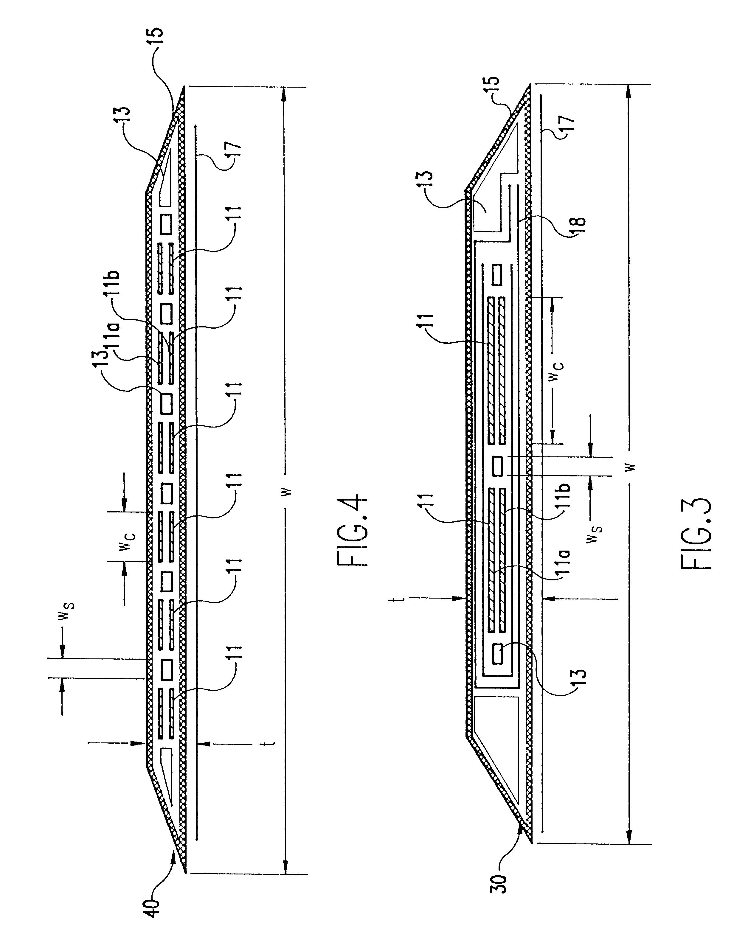
embodiment 40
An illustrative example of a telephone wire embodiment 40 according to the present invention is shown in FIG. 4. In this embodiment, six multi-layered copper conductors 11 are provided, separated by adhesive material 13, and surrounded by insulation layer 15. A six conductor wire facilitates the use of Private Branch Exchange (PBX) switching, thereby providing a private telecommunications exchange that includes access to a public telecommunications exchange. The conductors 11 are functionally equivalent to standard 22 gauge telephone wire.
Two, four, and eight multi-layered copper conductor telephone wires may also be utilized. Moreover, the eight conductor embodiment approximates four twisted pair wires (e.g., unshielded twisted pair (UTP) wire), which may be suitable for carrying data.
Each of the conductors 11 would generally have two or three copper layers, the former being shown by copper layers 11a and 11b in FIG. 4. The copper layers are about 0.0004 to about 0.020 inches thick...
embodiment 50
An illustrative example of a cable television CATV wire embodiment 50 in accordance with the present invention is shown in FIG. 5. In this embodiment, a pair of conductors 11 are provided, each of which may generally have two or three copper layers, the former being shown by copper layers 11a and 11b in FIG. 5. The copper layers are about 0.0004 to about 0.020 inches thick, and preferably on the order of about 0.002 inches thick. It is understood that, depending on the particular application, more or less copper layers may be utilized.
As in the previous embodiments, the conductors 11 are separated by adhesive material 13, and surrounded by insulation layer 15. As shown in FIG. 5, the edges of the wire 50 may be tapered to facilitate the optical occlusion. A similar external adhesive layer 17 as that previously described is also provided to attach the wire 50 to the appropriate surface.
The finished antenna / CATV wire 50, with three copper layers, is approximately 0.008 inches in cross...
PUM
| Property | Measurement | Unit |
|---|---|---|
| width | aaaaa | aaaaa |
| width | aaaaa | aaaaa |
| height | aaaaa | aaaaa |
Abstract
Description
Claims
Application Information