
Portable oxygen dispenser

a dispenser and oxygen technology, applied in the field of inhalers, can solve the problems of bending, damage to the stem of the canister, and the need to discard the contents, etc., and achieve the effects of reducing the risk of damage or breakage, and being convenient to us

Inactive Publication Date: 2002-12-17
WELIK RALPH
View PDF5 Cites 34 Cited by
  • Summary
  • Abstract
  • Description
  • Claims
  • Application Information

AI Technical Summary

Benefits of technology

It is yet another object of the invention to provide a portable oxygen dispenser which includes a protective guide on the conical diffusing member which eliminates or minimizes the risk of damage or breakage of the nozzle-stem of the aerosol valve during use.
It is a further object of the invention to provide a portable oxygen dispenser which is easier to use under various conditions without risk of damage to the valve stem which releases the oxygen or oxygen mixture.
It is still a further object of the invention to provide a portable oxygen dispenser which is simple in construction and economical to manufacturer.
It is yet a further object of the present invention to provide a portable oxygen dispenser which has a dual purpose diffuser member that can be used, on the one hand, to receive the oxygen from a cannister and diffuse it for intake by a user through the nose and / or mouth, and, on the other hand, to cover that end of the cannister which includes the cannister valve and nozzle stem and protects the same when not in use.
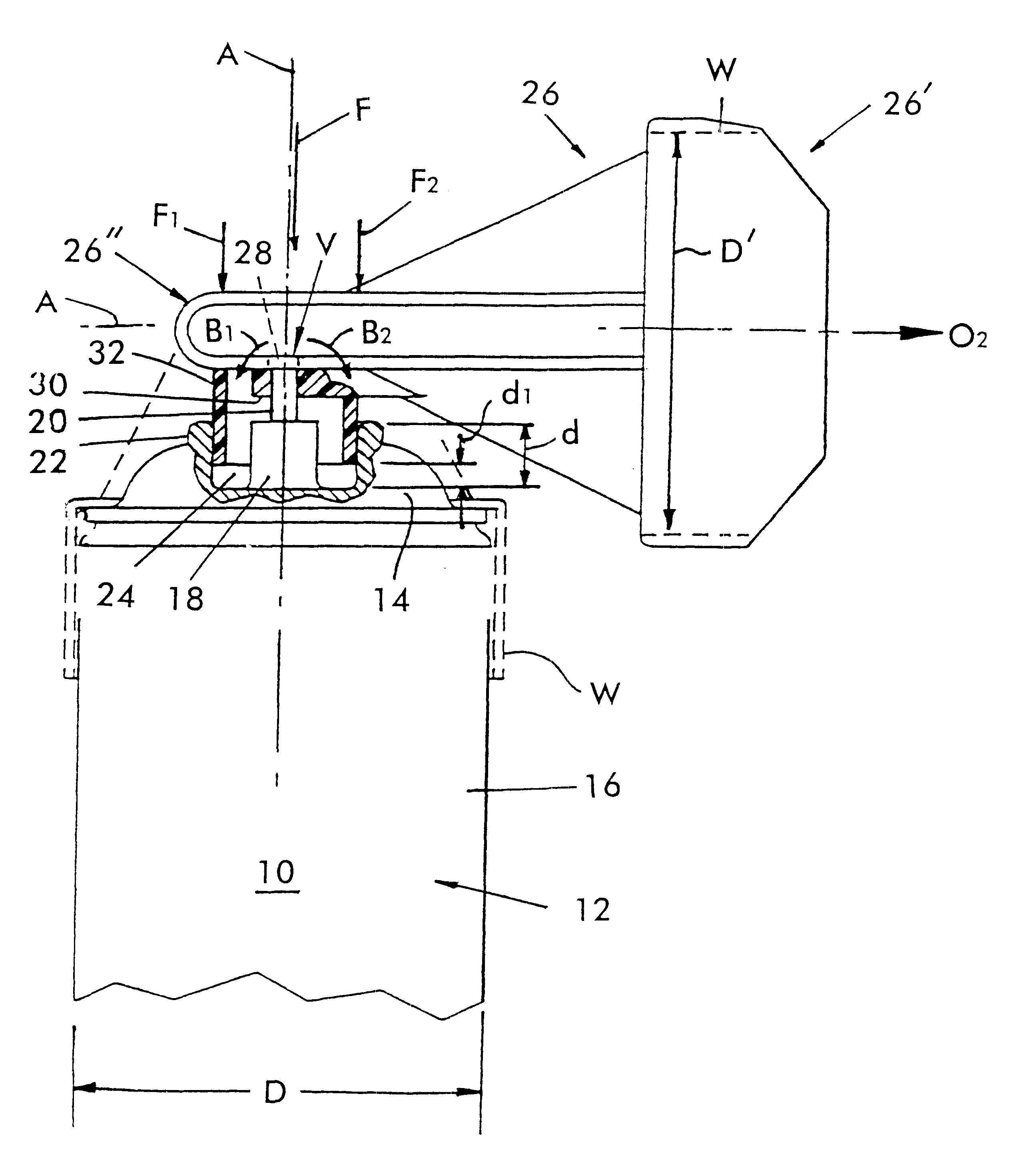
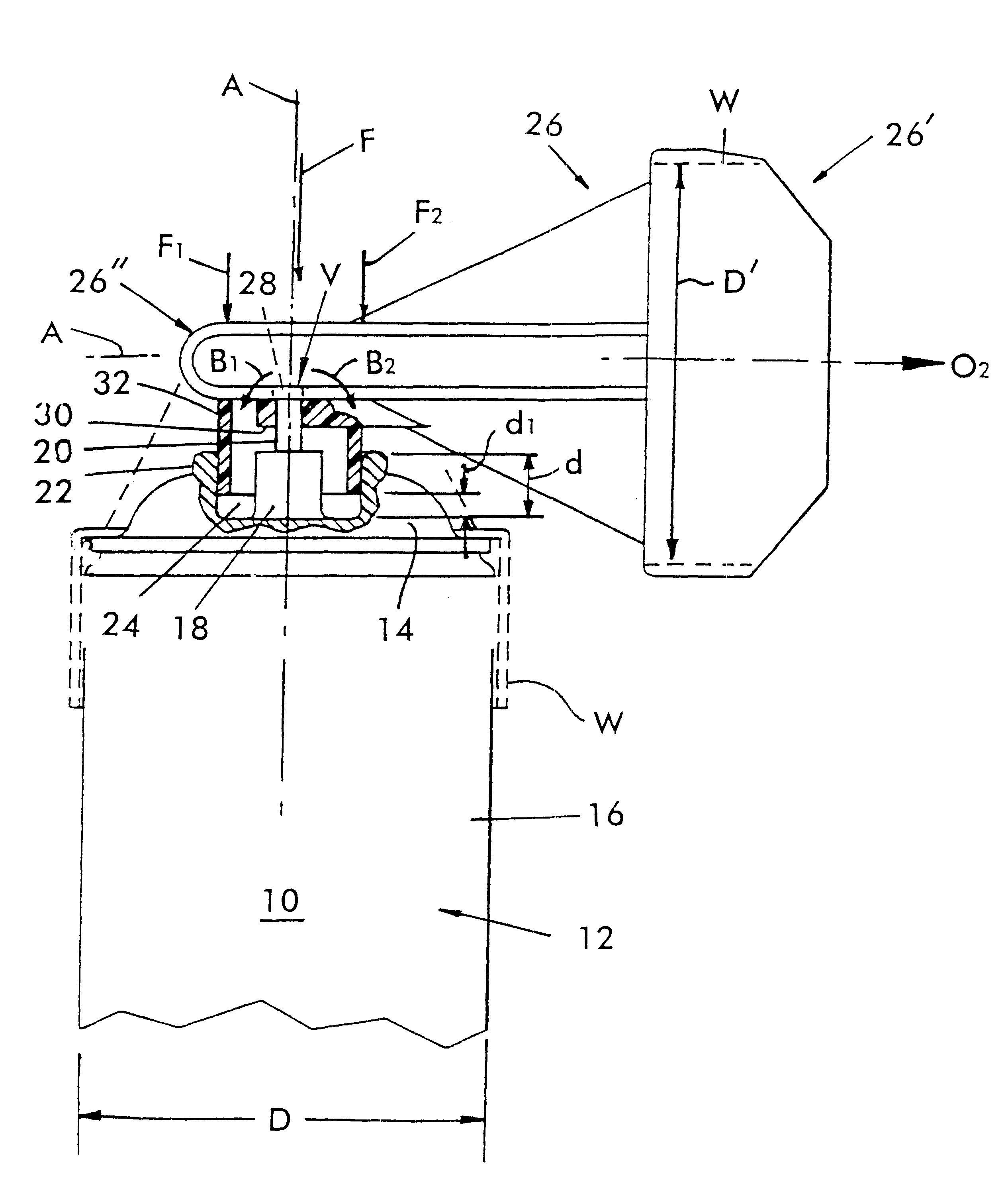
In order to achieve the above objects, as well as others which will become evident hereinafter, a portable oxygen dispenser in accordance with the present invention for providing an emergency supply of oxygen-rich gas comprises a closed cannister having a top closure portion in a cylindrical side wall defining a cannister axis in diameter and containing a quantity of oxygen-rich gas in a pressurized condition. A dispensing orifice includes an externally actuatable valve means at one axial end of said cannister for maintaining said dispensing orifice in a normally closed condition. Said valve means includes a nozzle stem generally arranged along said cannister axis for opening said orifice when an axial force is applied thereto. An annular neck wall is generally concentrically arranged about said nozzle stem and dimensioned to form an annular space between the nozzle stem and said neck wall. A generally conical diffusing member defines a diffusion axis and opposing axial ends, one of which is a dispensing open end dimensioned to substantially correspond to said cannister diameter, and the other end of which is a closed infusion end provided with an inlet opening defining an axis generally transverse to said diffusion axis and stem engaging means for selectively applying an axial force to said nozzle stem. Said one dispensing end is configured to fit over and be supported on said cannister when not in use, and said cannister and said diffusion axes are generally aligned and are adapted to be placed over the mouth and / or nose of a user. Protective guide means is provided extending from said closed infusion end along said transverse axis into said annular for slidingly engaging said annular neck wall with little clearance during use once said cannister and transverse axes are generally aligned and oxygen-rich gas is to be released and for substantially limiting forces applied to said nozzle stem to axial forces along said cannister axis. In this manner, forces on said nozzle stem other than said axial forces along said cannister axis are avoided, thereby to prevent damage to said nozzle stem during use of said diffusing member.

Problems solved by technology

One of the difficulties with aerosol cannisters generally is that they typically include a nozzle or valve stem which is frequently in the form of a thin-walled small diameter tube made of a deformable material, such as plastic.
Unfortunately, once the valve stem breaks, there is no other mechanism for opening the aerosol cannister valve and, therefore, the entire cannister and its contents must be discarded.
However, application of forces to the valve stem other than axial forces can cause bending and damage to such stem, as suggested.

Method used


Image

  • Portable oxygen dispenser
  • Portable oxygen dispenser

Examples


Embodiment Construction

Referring now to the FIGURE, a portable oxygen dispenser in accordance with the present invention for providing an emergency supply of oxygen-rich gas is generally designated by the reference numeral 10.

The dispenser 10 includes a closed aerosol container or cannister 12. The cannister 12 is generally a right cylindrical cannister having a circular cross section defining a cannister axis A. The cannister 12 has a top closure portion in the form of a top wall 14 and a cylindrical side wall 16 defining a cannister diameter D and contains a quantity of oxygen-rich gas in a pressurized condition.

A conventional dispensing orifice 18 is formed in the top wall 14 which includes an externally actuatable valve V at one axial end of the cannister, as shown in the FIGURE, for maintaining the dispensing orifice in a normally closed condition. Such dispensing orifice or valve is well known and is used with conventional aerosol cannisters or containers for dispensing various substances, typically...


PUM


Abstract

A portable oxygen dispenser for providing an emergency supply of oxygen-rich gas includes a closed cannister defining a cannister axis and diameter and containing a quantity of pressurized, oxygen-rich. A dispensing orifice includes an externally actuable valve at one axial end of said cannister for maintaining the orifice normally closed. The valve includes a nozzle stem generally arranged along the cannister axis. An annular neck wall is generally concentrically arranged about the nozzle stem and dimensioned to form an annular space between the nozzle stem and the neck wall. A generally conical diffusing member defines a diffusion axis and opposing axial ends, one of which is a dispensing open end dimensioned to substantially correspond to the cannister diameter; the other end is a closed infusion end and is provided with an inlet opening defining an axis generally transverse to the diffusion axis and structure for engaging the stem for selectively applying an axial force to the nozzle stem. The dispensing end is configured to fit over the cannister when not in use. The cannister and the diffusion axes are generally aligned and adapted to be placed over the mouth and / or nose of a user. A protective guide extends into the annular space slidingly engaging the annular neck wall for substantially limiting the forces applied to the nozzle stem to axial forces along the cannister axis. In this way, forces on the nozzle stem other than the axial forces along the cannister axis are avoided, thus preventing damage to the nozzle stem during use of the diffusing member.

Description

1. Field of the InventionThis invention generally relates to inhalers and, more particularly, to a portable oxygen dispenser.2. Description of the Prior ArtActuators for aerosol inhalers of various types have been proposed. In most instances, the devices are used for dispensing medicinal aerosol formulations. See, for example, U.S. Pat. No. 5,899,201. A dispensing package for material under pressure is also disclosed in U.S. Pat. No. 3,012,555. In these patents actuators are disclosed for specialized cannisters used for storing drugs for treating various disorders such as asthma, chronic bronchitis, emphysema and chronic obstructive pulmonary disease. The specialized cannisters are relatively small, and the actuators are designed to actuate the nozzle valve while engaging the outside rim or periphery of the cannister. In such cases, the actuator typically has a cylindrical housing portion the inner surface of which engages the outside rim or periphery of the cannister. This is also ...

Claims


Application Information

Patent Timeline
IPC IPC(8): A61M15/00A62B7/00A62B7/02A61M16/00
CPCA61M15/009A62B7/02A61M16/00A61M2202/0208
Inventor WELIK, RALPH
Owner WELIK RALPH
Learn More