Terminal that provides connection between a wire circuit and a printed circuit, and electric junction box including said terminal

a technology of printed circuits and terminals, which is applied in the direction of electrical devices, electrical apparatus casings/cabinets/drawers, contact members penetrating/cutting insulation/cable strands, etc., can solve the problems of difficult to satisfactorily connect covered wires and printed circuits, difficult to efficiently radiate to outside the housing, and compact size and simplification of their structur

Inactive Publication Date: 2002-12-17
AUTONETWORKS TECH LTD +2
View PDF12 Cites 86 Cited by
  • Summary
  • Abstract
  • Description
  • Claims
  • Application Information

AI Technical Summary

Problems solved by technology

For the above-described reasons, with the conventional electric junction box, its compact size and simplification of its structure are considered difficult, and drastic measures for them have been important tasks.
However, if the wiring materials are merely selected in correspondence with the current values, it has been difficult to satisfactorily connect the covered wires and the printed circuits.
Here, with the structure in which the relay block 106 is interposed in the bus bar circuit unit in the conventional manner, even if the relay block 106 is simply substituted by the semiconductor switching devices, it is extremely difficult to efficiently radiate to outside the housing the heat generated by the semiconductor switching devices which are disposed in a distributed manner in the bus bar circuit unit, and this has been a major obstacle to the introduction of the semiconductor switching devices.

Method used


Image

  • Terminal that provides connection between a wire circuit and a printed circuit, and electric junction box including said terminal
  • Terminal that provides connection between a wire circuit and a printed circuit, and electric junction box including said terminal
  • Terminal that provides connection between a wire circuit and a printed circuit, and electric junction box including said terminal

Examples


first embodiment

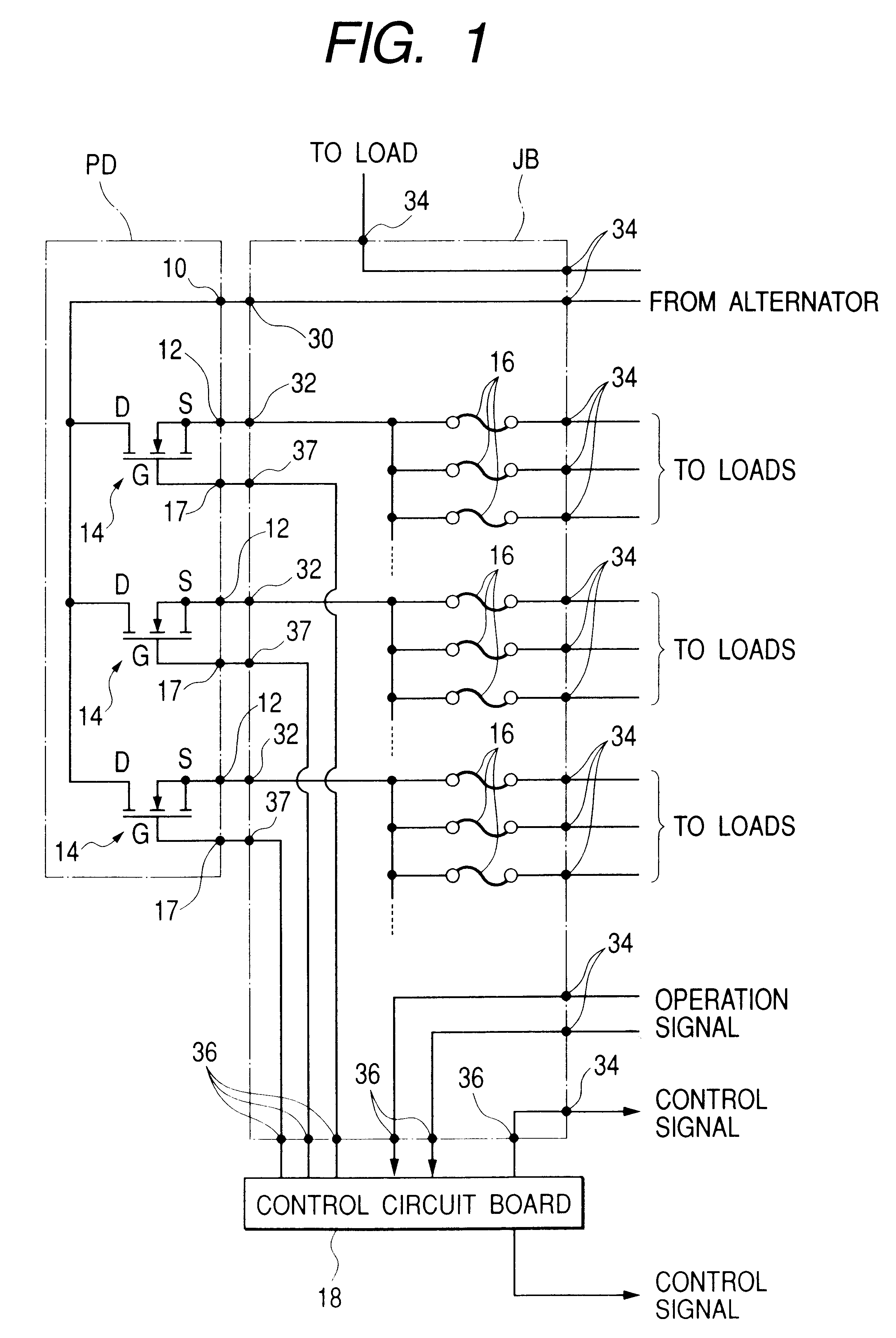
First, referring to FIG. 1, a description will be given of a circuit configuration of an electric junction box for a vehicle in accordance with a first embodiment.

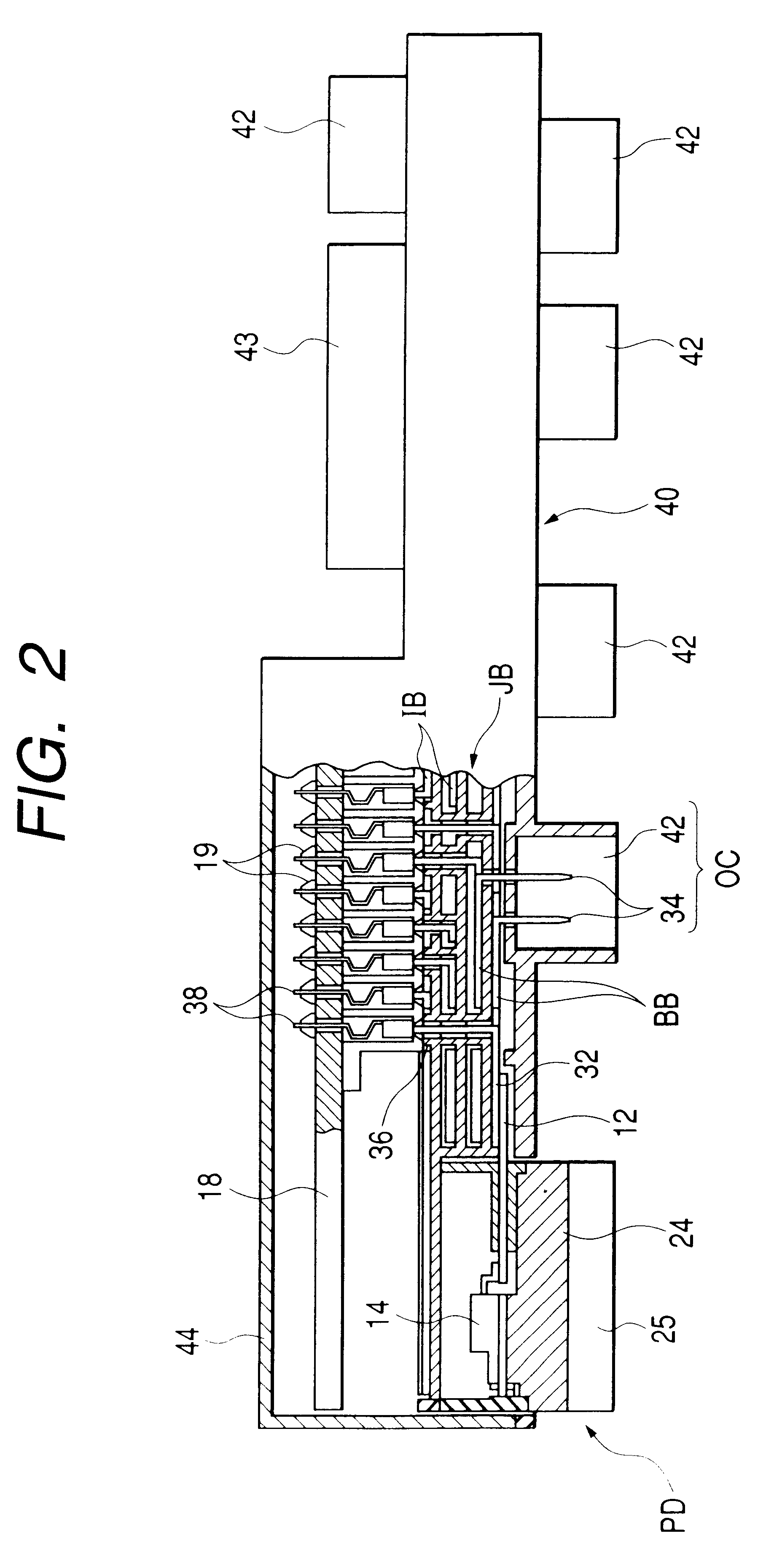
The circuitry concerning this electric junction box is comprised of a power distributing unit PD connected to a vehicle-mounted power source (a battery in the drawing), a bus bar circuit unit JB configured by a bus bar board, and a control circuit board 18.

The power distributing unit PD has an input terminal 10 which is connected to the battery, a plurality of (three in the illustrated example) output terminals 12, controlling terminals 17 in the same number, and semiconductor switching devices (MOSFETs 14 in the illustrated example, hereafter simply referred to as "FETs") are respectively interposed between the input terminal 10 and the respective output terminals 12. Specifically, an input-side energizing terminal (drain) of each FET 14 is connected to the common input terminal 10, an output-side energizing terminal (sou...

second embodiment

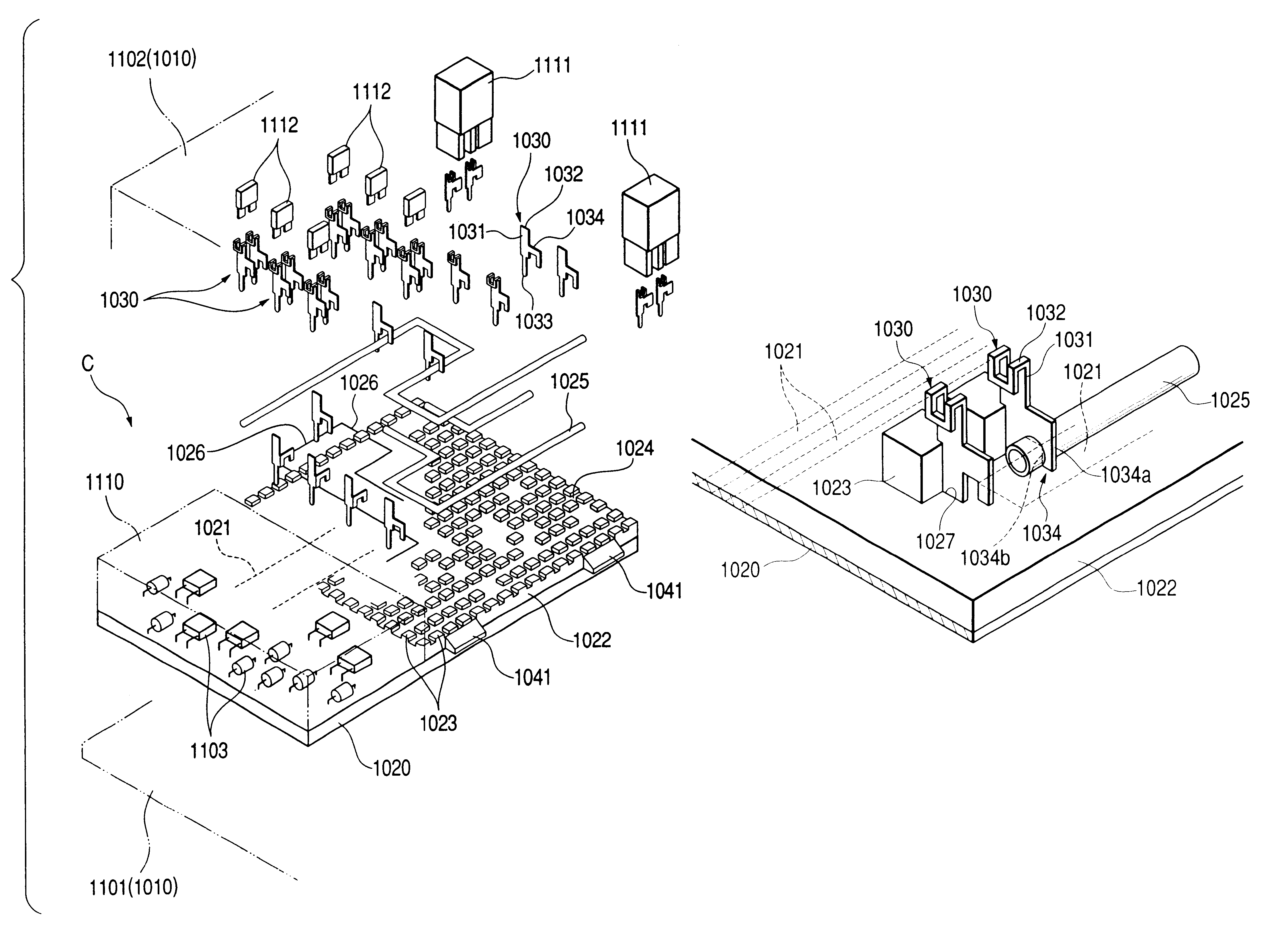
FIG. 7 is an exploded perspective view illustrating essential portions of an electric junction box in accordance with a second embodiment of the invention.

Referring to FIG. 7, an internal circuit C of the electric junction box in accordance with the second embodiment has a printed circuit board 1020. On this printed circuit board 1020, a control unit 1110 having electronic components 1103 is formed on its portion (on a left-hand portion in the drawing). A printed circuit 1021 (a small-current portion of the internal circuit C) is formed on the reverse surface (an internal layer in the case of a multi-layered type) of the printed circuit board 1020.

A wire circuit board 1022 is mounted on an upper surface of the printed circuit board 1020. The wire circuit board 1022 together with the printed circuit board 1020 constitutes an electrical wiring board. A multiplicity of rectangular projections 1023 arranged in a checkered pattern are projectingly formed on the upper surface of the wire ...


PUM


Abstract

A terminal is mounted on an electric wiring board that has both a wire circuit formed by a wire and a printed circuit formed by a printed conductor. The terminal includes a connecting portion capable of electrically connecting an internal circuit of the electric wiring board to an external circuit, a lead portion capable of being electrically connected to the printed circuit of the electric wiring board, and a press-fitting portion capable of being electrically connected to the wire circuit. The electric wiring board may be mounted in an electric junction box. A load supporting member may be provided which transfer a load acting on the terminal from a connector of the external circuit to the housing. The load supporting member may include an engaging portion provided at an end surface of a wiring circuit board, and a retaining portion provided on a side wall of the housing.

Description

1. Field of the InventionThe present invention relates to an electric junction box and terminals used in the electric junction box. The electric junction box is used for a vehicle for electrically connecting a plurality of vehicle-mounted loads to a power source such as a battery mounted therein.2. Description of the Related ArtConventionally, as an electric junction box provided in a vehicle, one is generally known which is provided with a bus bar board in which each group of metallic bus bars and each of insulating plates are alternately laminated, and a vehicle-mounted power source (e.g., a battery) is connected to a multiplicity of vehicle-mounted loads (electrical apparatuses) through bus bar circuits formed by the bus bar board. Further, a mechanical relay block is incorporated in the bus bar board such that current between the vehicle-mounted power source and the loads can be subjected to on / off switching midway thereof, as required.FIG. 13 illustrates an example of a structu...

Claims


Application Information

Patent Timeline
Patent Type & Authority Patents(United States)
IPC IPC(8): B60R16/02H05K7/02H02G3/08H01R4/24H01R9/22H05K3/40H05K3/20H05K3/32B60R16/023H01R12/04
CPCB60R16/0238H05K7/026H01R4/242H01R9/226H02G3/08H05K3/202H05K3/328H05K3/4092Y10S439/907
Inventor YAMANE, SHIGEKIONIZUKA, TAKAHIROISSHIKI, ISAO
Owner AUTONETWORKS TECH LTD
Why Eureka
Try Eureka