Method and device for measuring dielectric constant

Inactive Publication Date: 2002-12-17
OJI PAPER CO LTD
View PDF13 Cites 44 Cited by
  • Summary
  • Abstract
  • Description
  • Claims
  • Application Information

AI Technical Summary

Problems solved by technology

However, with this method, there is a problem that it is difficult to measure an opaque liquid such as heavy oil that can hardly transmit light There is also such a prob

Method used


Image

  • Method and device for measuring dielectric constant
  • Method and device for measuring dielectric constant
  • Method and device for measuring dielectric constant

Examples


example 1

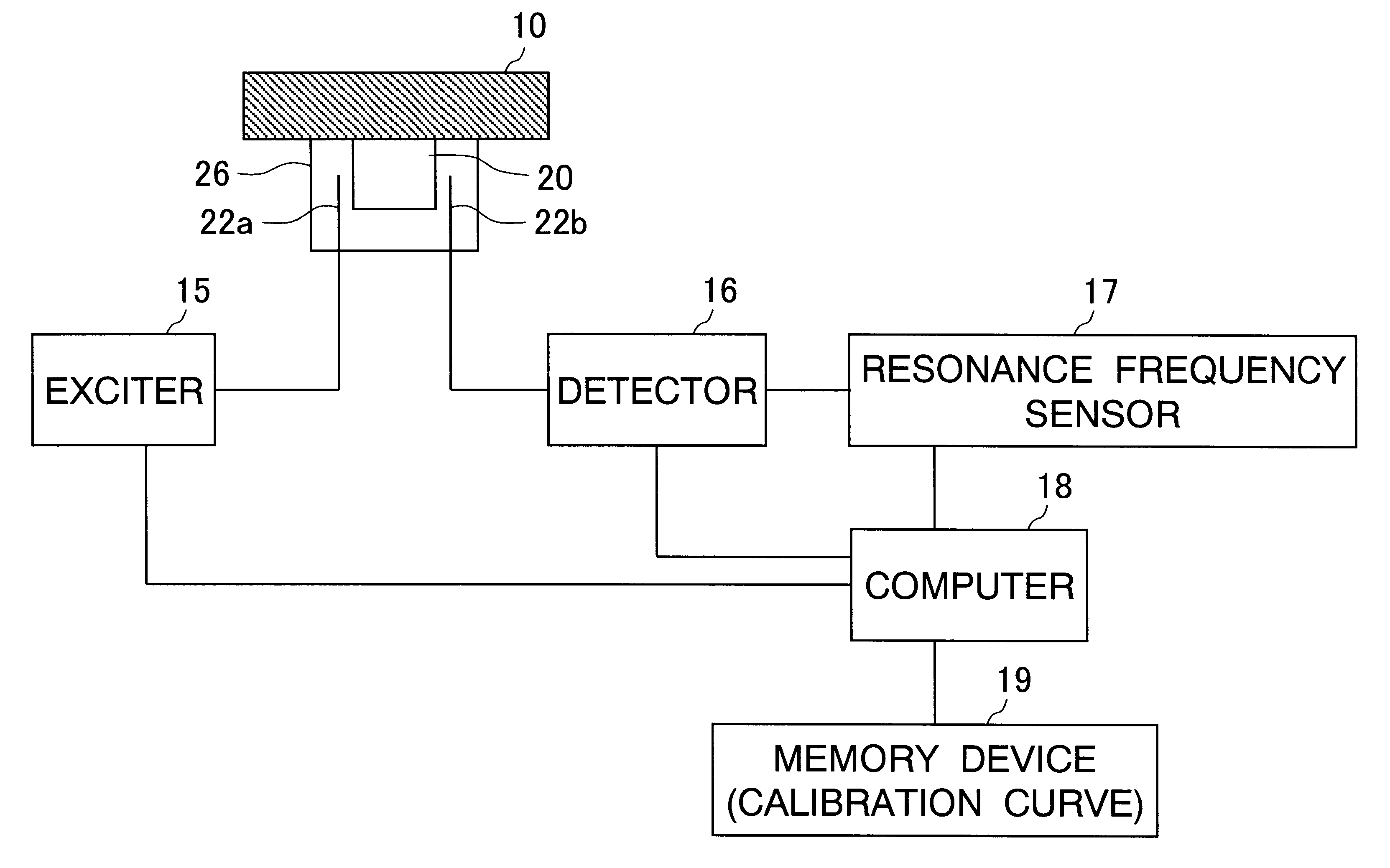
FIG. 7 shows one Example of the present invention, exhibiting a sectional view in a case of bringing a sample into contact with a dielectric resonator and measuring the same. The dielectric resonator itself is identical in structure to that shown in FIG. 5. A square dielectric resonator 20 of 20.84 in dielectric constant is mounted with the bottom surface along the horizontal direction in a shielding brass vessel 26 of which the upper part is open. The dielectric resonator 20 is so set that its upper surface is substantially flush with an edge of the opening of the shielding vessel 26, and a sample 10 is placed to block the opening of the shielding vessel 26. An excitation antenna 22a and a detection antenna 22b are rod antennas, which are set between the shielding vessel 26 and the dielectric resonator 20.

Three polyethylene (PE) boards of 100 mm by 100 mm having a thickness of 2 mm as a sample 10 are brought into contact with this dielectric resonator 20. The antennas 22a and 22b o...

example 2

To improve the Q value (sharpness of resonance) of a dielectric resonator, a spacer 30 was interposed between the bottom surface of the dielectric resonator 20 and a shielding vessel 30, as shown in FIG. 12. Referring to FIG. 12, (A) is a plan view, and (B) is a vertical sectional view of (A). The relation between the thickness of the spacer 30 and the Q value varied as shown in FIG. 13 when making resonance of a TM.sub.201 mode at 4 GHz. Referring to FIG. 13, (A) shows a case where the spacer 30 is a metal sheet, and (B) shows a case where the spacer 30 is a PET (polyethylene terephthalate) film. It is understood from these results that the thickness of the spacer 30 is optimally around 0.5 mm for improvement of the Q value.

FIG. 14 shows results obtained by measuring the difference between Q values responsive to presence / absence of the spacer 30. The horizontal axis shows frequencies, and the vertical axis shows microwave transmission intensity. (A) shows a case of interposing the ...


PUM


Abstract

The sample measuring face of a dielectric resonator (20) is placed near a standard sample having a known dielectric constant at a fixed interval D. While appropriately varying the dielectric constant and thickness of the standard sample under the above condition, the variation of the resonance frequency of the dielectric resonator (20) is measured for each varied dielectric constant and thickness to draw a calibration curve of the varied resonance frequency depending on the dielectric constant and thickness. Under the same condition where calibration curve is drawn, the variation of the resonance frequency of the dielectric resonator (20) for a sample having a known thickness is measured. The dielectric constant of the sample is found from the measurement value and the calibration curve. The dielectric constant of not only a sheetlike sample but also a three-dimensional molded article or a liquid sample can be measured easily.

Description

The present invention relates to a method and a device for measuring dielectric constants by microwaves, of sheetlike substances such as a high-polymer sheet and paper including film, and three-dimensional articles such as moldings of plastic, resin, rubber and the like, as well as liquids such as an aqueous solution, a water dispersion liquid, an organic solvent liquid, liquid organic matter and the like.TECHNICAL BACKGROUNDA dielectric constant is a physical value based on polarization in the inner part of a substance similar to a refractive index, and considered as an important physical value since the same is closely connected with electric, optical and dynamic physical properties. In a high-frequency domain such as light, the refractive index and the dielectric constant are in the relation:(refractive index).sup.2 =dielectric constantand, hence, it is also possible to make substitution by either one as the case may be. For a transparent substance, refractive index measurement b...

Claims


Application Information

Patent Timeline
IPC IPC(8): G01N22/00G01R27/26
CPCG01N22/00G01R27/2617
Inventor NAGATA, SHINICHIMIYAMOTO, SEIICHIOKADA, FUMIAKI
Owner OJI PAPER CO LTD
Why Eureka
Try Eureka