Method for calibrating a smart-antenna array radio transceiver unit and calibrating system

a radio transceiver and smartantenna array technology, applied in the direction of antennas, radio wave direction/deviation determination systems, direction finders, etc., can solve the problems of shortening the life of the battery, affecting the service life of the mobile terminals served by the base station, and affecting the service life of the active or semi-active components

Inactive Publication Date: 2002-12-17
NOKIA TECHNOLOGLES OY
View PDF7 Cites 50 Cited by
  • Summary
  • Abstract
  • Description
  • Claims
  • Application Information

AI Technical Summary

Problems solved by technology

When employed in a base station, the output power of mobile terminals served by the base station can be decreased due to the spatial gain, which results in a longer battery lifetime.
A disadvantage of the described calibration system, however, results from the switching us...

Method used


Image

  • Method for calibrating a smart-antenna array radio transceiver unit and calibrating system
  • Method for calibrating a smart-antenna array radio transceiver unit and calibrating system
  • Method for calibrating a smart-antenna array radio transceiver unit and calibrating system

Examples


Embodiment Construction

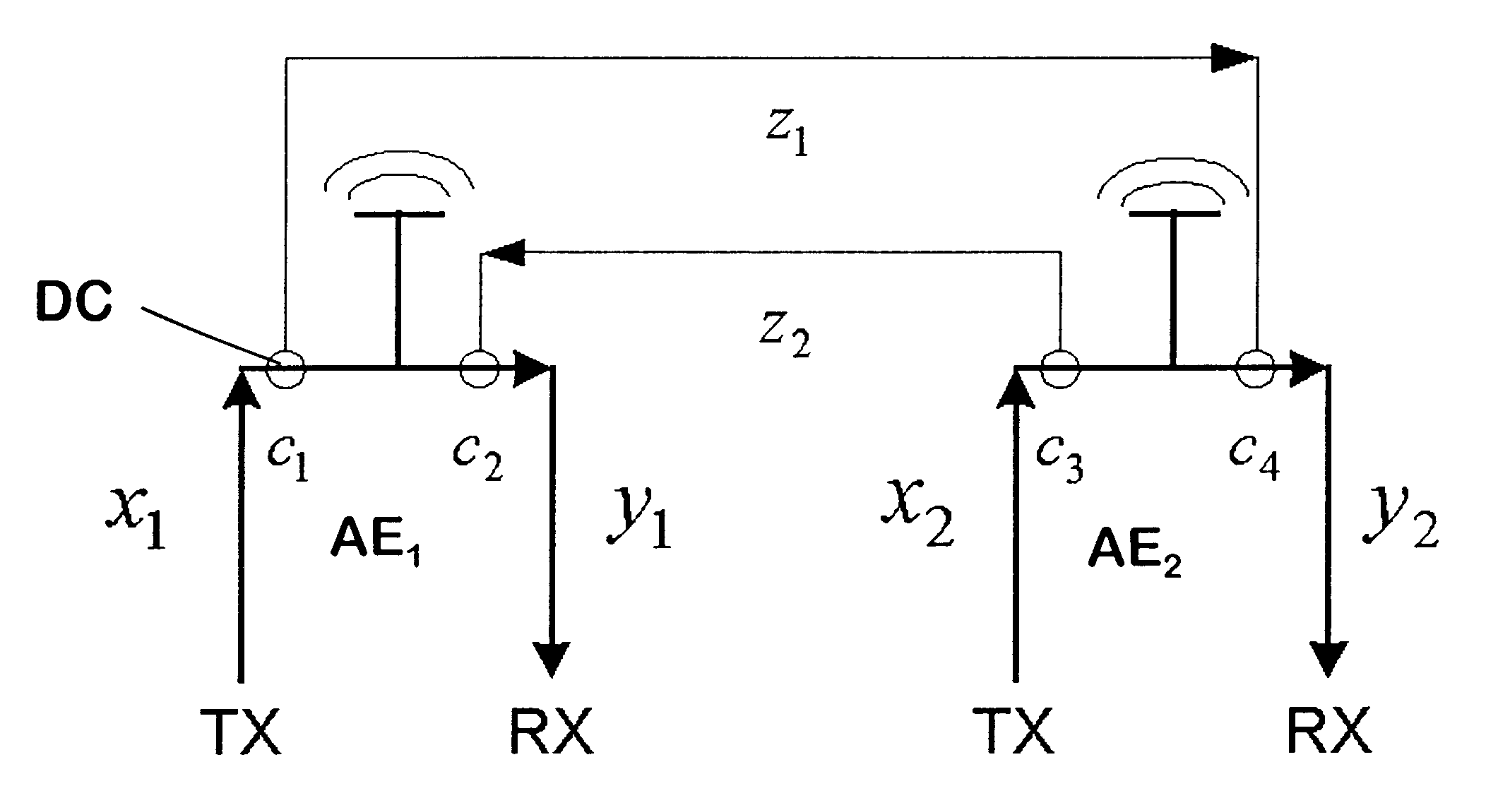
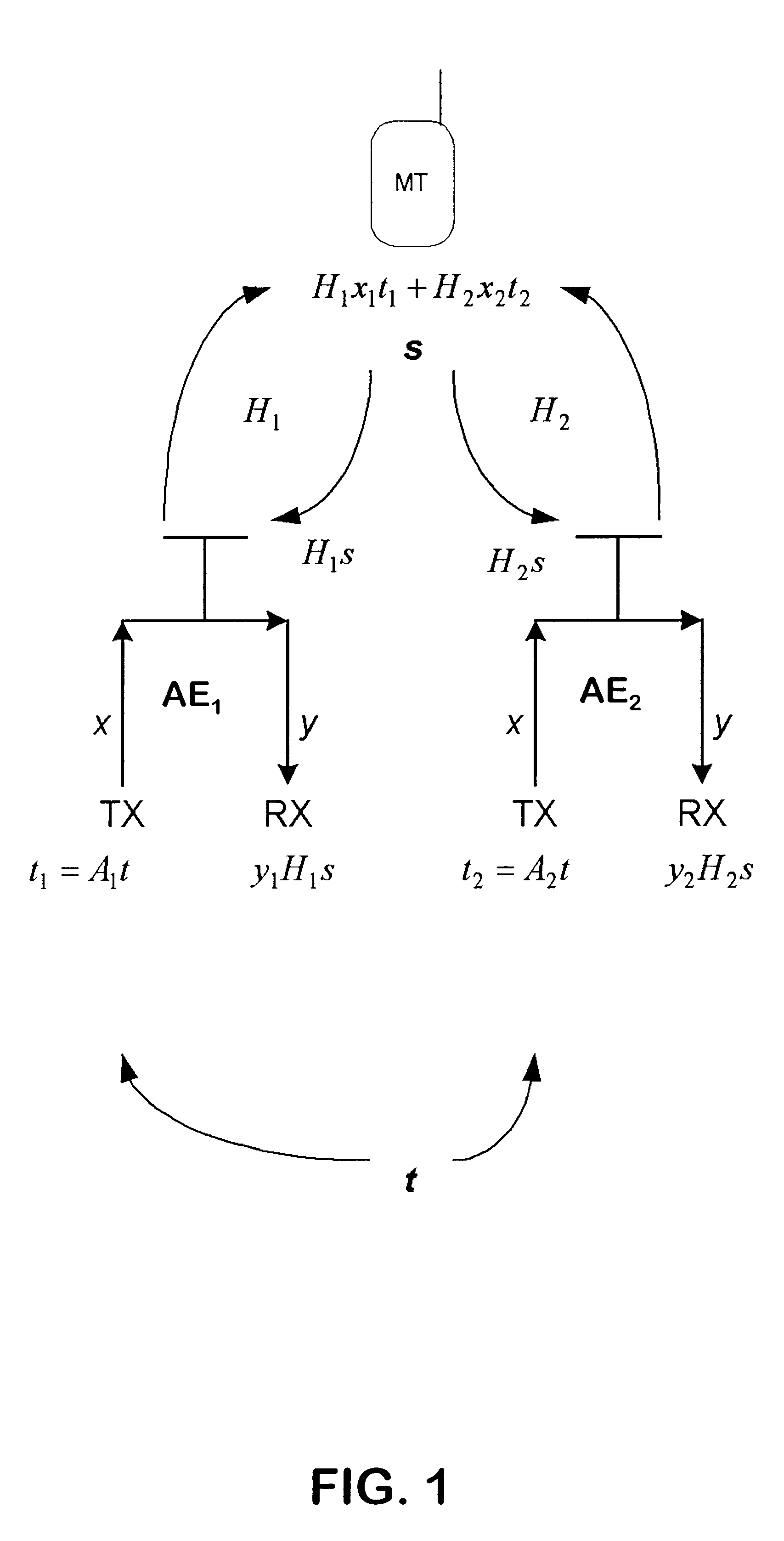
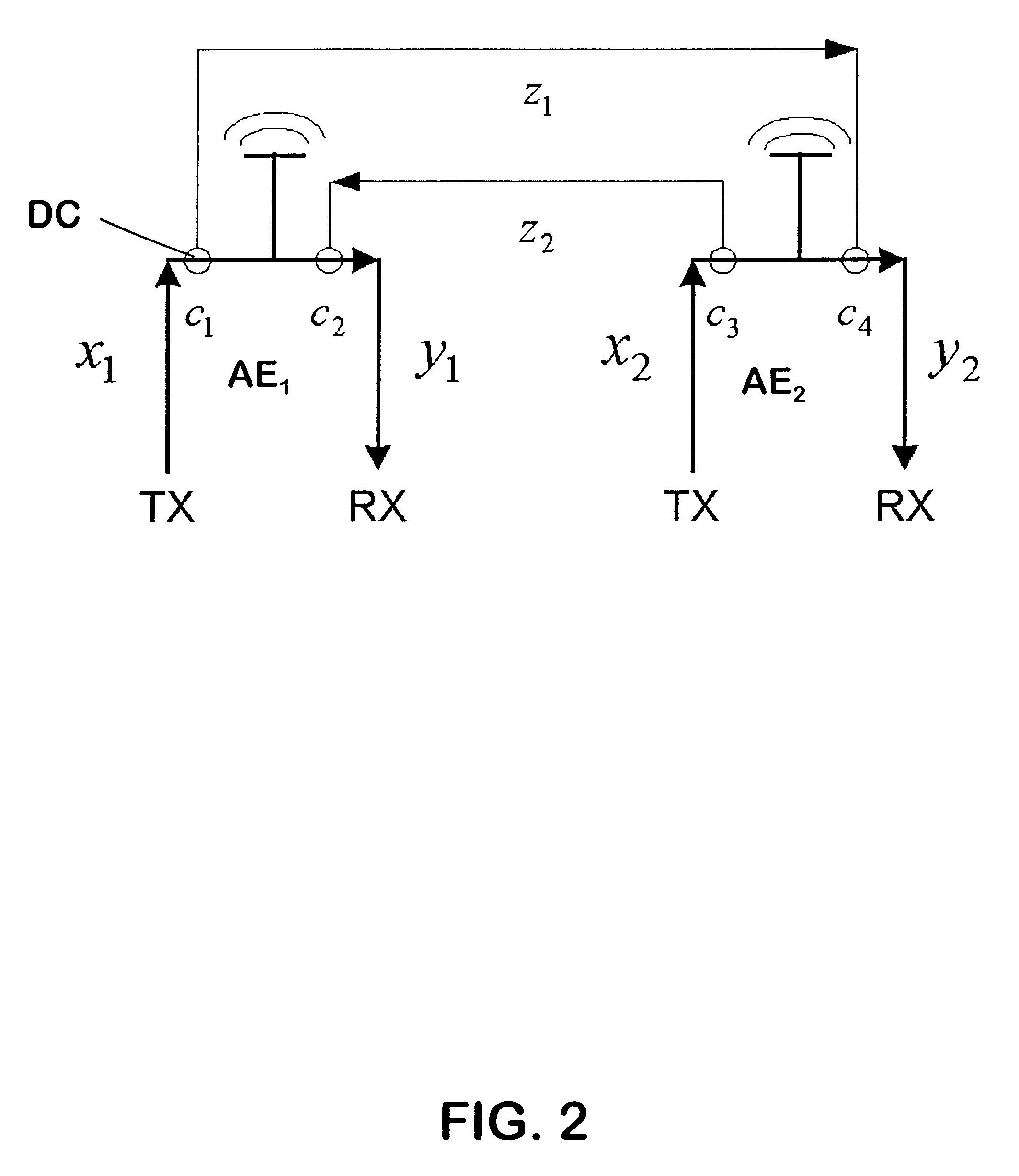
FIG. 1 schematically shows a part of a wireless communications system using TDD.

Of the wireless communications system, two antenna elements AE.sub.1, AE.sub.2 of a smart antenna system and a mobile terminal MT are depicted. The smart antenna system is implemented in a base station of a radio access network. Each of its antenna elements AE.sub.1, AE.sub.2 comprises a transmit TX and a receive RX radio frequency branch between which can be switched for transmission and reception. The transmit TX branches are connected within the base station to a common transmitter (not shown) operating at the baseband, and the receive RX branches are connected to a common receiver (not shown) operating at the baseband. The mobile terminal MT, which is located in the serving area of the base station, only uses a single antenna element. The transfer functions, or properties, of the radio channel between the first antenna element AE.sub.1 and the mobile terminal MT are referred to as H.sub.1, and the tr...


PUM


Abstract

The invention relates to a method for calibrating a smart-antenna array of a wireless access system using TDD, which antenna array comprises antenna elements with a transmit and a receive branch each. In order to enable a time stable calibration, it is proposed that at least some of the antenna elements are selected in turns to be employed for transmitting broadcast messages. This provides time periods in which only one of said elements is transmitting. Each transmit branch is connected to at least one of the receive branches of another element, signals transmitted via these connections being evaluated for calibration. If receive branches are connected to transmit branches of several elements, it is ensured with the proposed selection that during the broadcast periods these receive branches receive at the most a signal from one element, thus avoiding the need for switches. The invention equally relates to a corresponding radio transceiver unit and a corresponding calibration system.

Description

1. Field of the InventionThe invention relates to a method for calibrating a smart-antenna array of a time division duplex (TDD) system, which smart antenna comprises an array of at least two antenna elements, each with a transmit (TX) and a receive (RX) radio frequency branch. The invention equally relates to a radio transceiver unit with a smart antenna array for a wireless access system using time division duplex, and to a calibrating system for calibrating a smart antenna array of a wireless access system using time division duplex.2. Description of the Related ArtSmart antennas are known to be employed as transmit and receive antennas in wireless access systems, in particular in base stations of such systems. Smart antennas, which generally use an array of antenna elements, enable the output of fully steerable beams patterns. They can be employed for example for a user specific digital beamforming, in which a beamformer of the smart antenna array is able to weight phase angle a...

Claims


Application Information

Patent Timeline
IPC IPC(8): H01Q3/26
CPCH01Q3/267
Inventor ALASTALO, ARI
Owner NOKIA TECHNOLOGLES OY
Why Eureka
Try Eureka