Solid state liquid level sensor and pump controller

a liquid level sensor and liquid level controller technology, applied in the direction of pump control, level control, instruments, etc., can solve the problems of low power consumption, large power consumption, and low power consumption during pumping

Inactive Publication Date: 2002-12-31
TECUMSEH PROD CO
View PDF58 Cites 71 Cited by
  • Summary
  • Abstract
  • Description
  • Claims
  • Application Information

AI Technical Summary

Problems solved by technology

This transformer / multiple relay configuration results in substantial power consumption, even in a standby condition when the pump is not active.
The other supply is used to activate an alarm through an alarm relay, but only consumes power when the alarm is activated.
This solid-state circuit is reliable in operation and consumes low power during pumping and when in the standby condition.

Method used


Image

  • Solid state liquid level sensor and pump controller
  • Solid state liquid level sensor and pump controller
  • Solid state liquid level sensor and pump controller

Examples


Embodiment Construction

The embodiments disclosed below are not intended to be exhaustive or to limit the invention to the precise forms disclosed. Rather, the embodiments are disclosed to enable one skilled in the art to practice the invention.

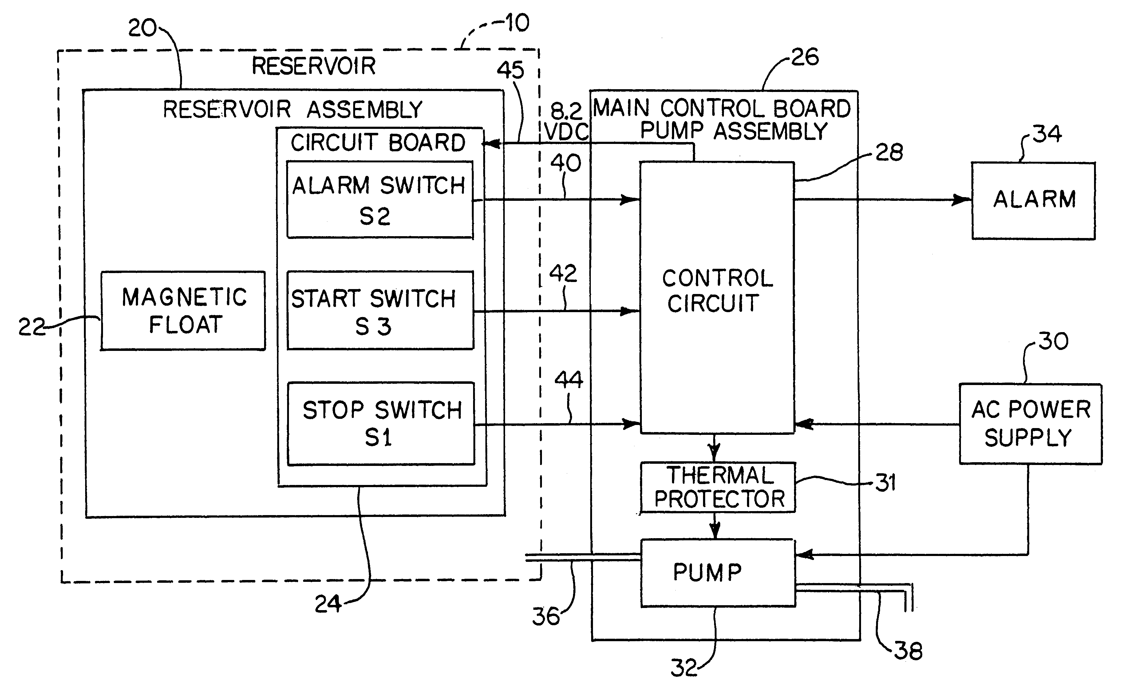
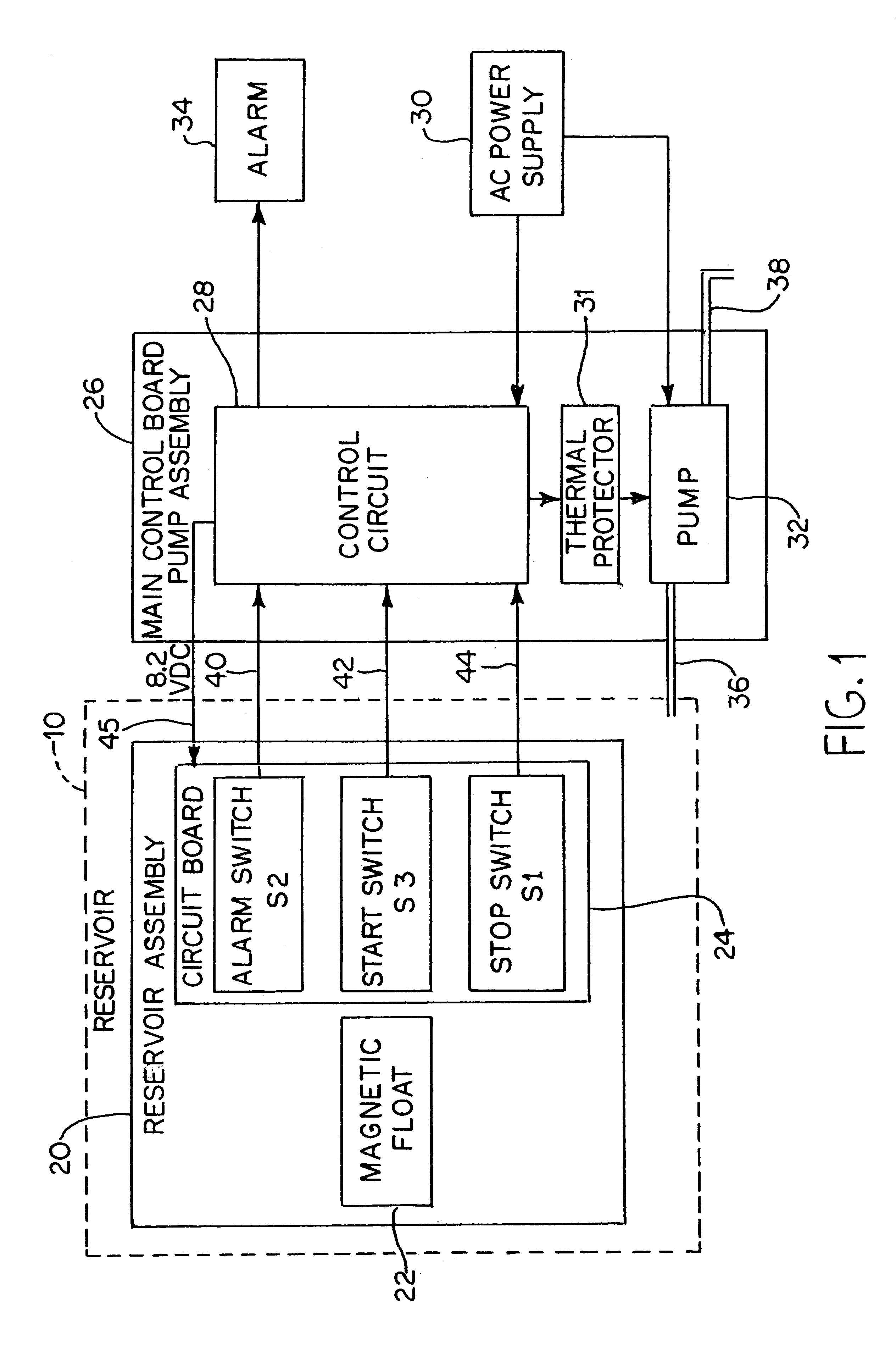
Referring to FIG. 1, a liquid level controller according to the present invention is used to control the liquid level in an enclosed reservoir 10. The controller generally includes a reservoir assembly 20 and a circuit board referred to as a control board / pump assembly 26.

Reservoir assembly 20 is disposed within reservoir 10 and includes a magnetic float 22 and a circuit board 24 to which are mounted reed switches S1, S2, and S3. Reed switches S1, S2, S3 are electrically connected to control board / pump assembly 26 by wires 40, 42, 44. Wire 45 carries 8.2 VDC from control board / pump assembly 26 to circuit board 24.

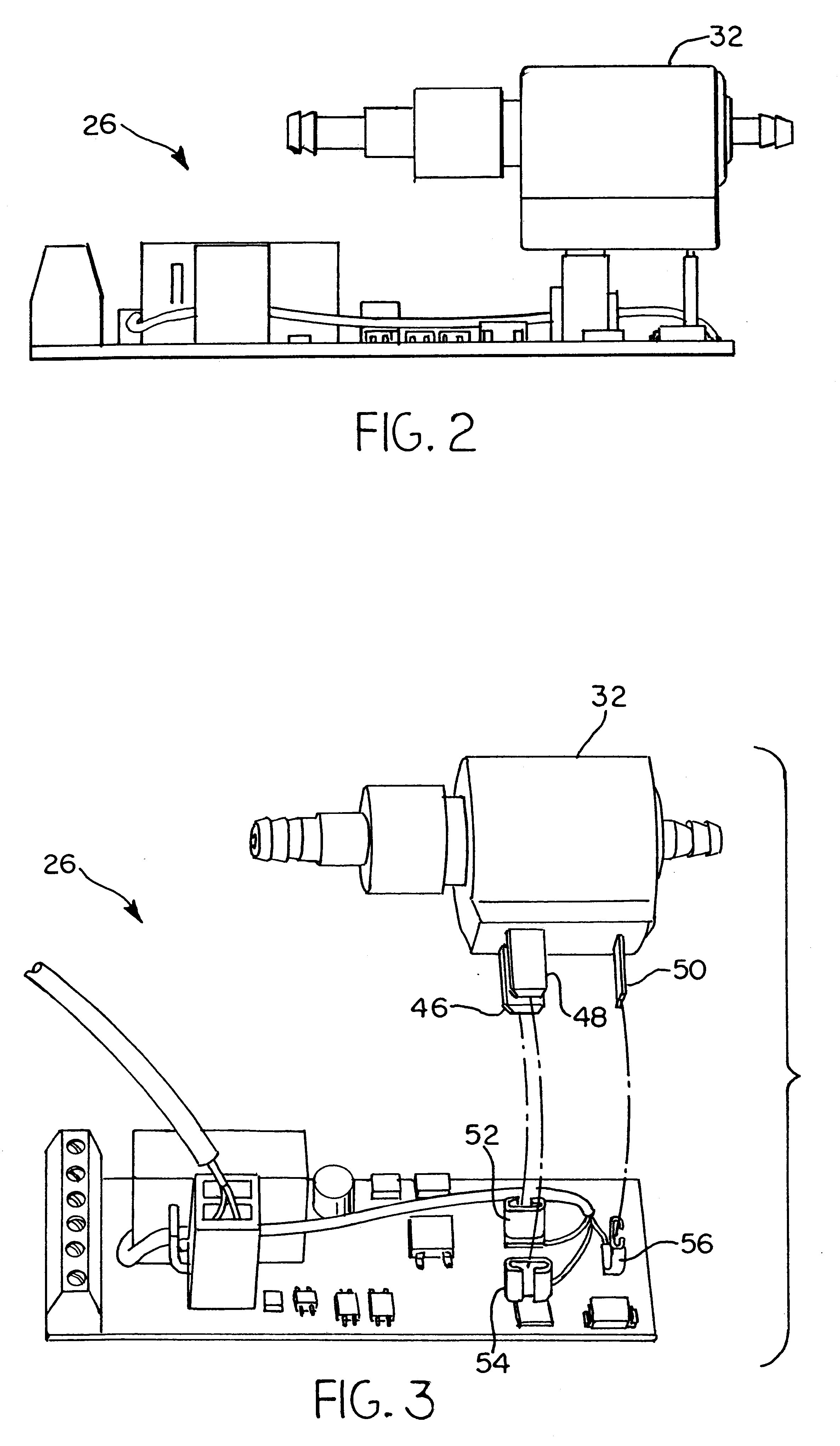
Control board / pump assembly 26 generally includes a control circuit 28, a thermal protector 31, and a pump 32. Thermal protector 31 and pump 32 are encapsu...


PUM


Abstract

A liquid level controller for a device having a liquid reservoir includes a control board and a reservoir assembly. The reservoir assembly is disposed within the reservoir and includes a liquid level sensor, which is electrically connected to the control circuit. The control board includes a control circuit and a pump. The control circuit has a control circuit and a resistive power supply to power the control circuit. The control circuit controls the pump in response to signals from the level sensor and includes a CMOS logic gate and a MOSFET transistor to switch the pump. The control circuit further includes a second resistive power supply connected to a relay which controls an alarm. The second power supply is activated by a transistor responsive to an alarm signal from the level sensor, and powers the relay only when the alarm signal is present.

Description

1. Field of the Invention.The present invention relates generally to a control circuit for a pump motor, and more particularly to a liquid level control circuit which automatically maintains the liquid level in a reservoir within a predetermined range.2. Description of the Related Art.Previous liquid level controlling devices typically include three separate assemblies: a reservoir assembly, a pump assembly, and a main control board. The reservoir assembly uses a magnet float / magnetic reed switch configuration to sense the level of liquid in the reservoir. Three magnetic reed switches situated within the reservoir at different levels provide signals to the main control board when the liquid level brings the magnetic float into proximity with the switches. These signals activate and deactivate a separately packaged, thermally protected, electrically isolated pump to adjust the liquid level. The main control board uses a power transformer to derive power for its electronics and an ele...

Claims


Application Information

Patent Timeline
Patent Type & Authority Patents(United States)
IPC IPC(8): F04B49/02F04B49/025G05D9/00G05D9/12
CPCF04B49/025G05D9/12
Inventor WYATT, ARNOLD G.TERRY, ROBERT L.
Owner TECUMSEH PROD CO
Why Eureka
Try Eureka