

Optical interferometer with a casing and an optical part that is movable with respect to the casing
a technology of optical interferometer and optical part, which is applied in the field of optical interferometer, can solve the problems of inability to carry out mechanical adjustment and optical adjustment, limit the downsizing of optical interferometer and shorten the measurement time, and inability to carry out good maintenance of optical interferometer, such as the repair of the moving member or the exchange thereo
- Summary
- Abstract
- Description
- Claims
- Application Information
AI Technical Summary
Problems solved by technology
Method used
Image

Examples
first embodiment
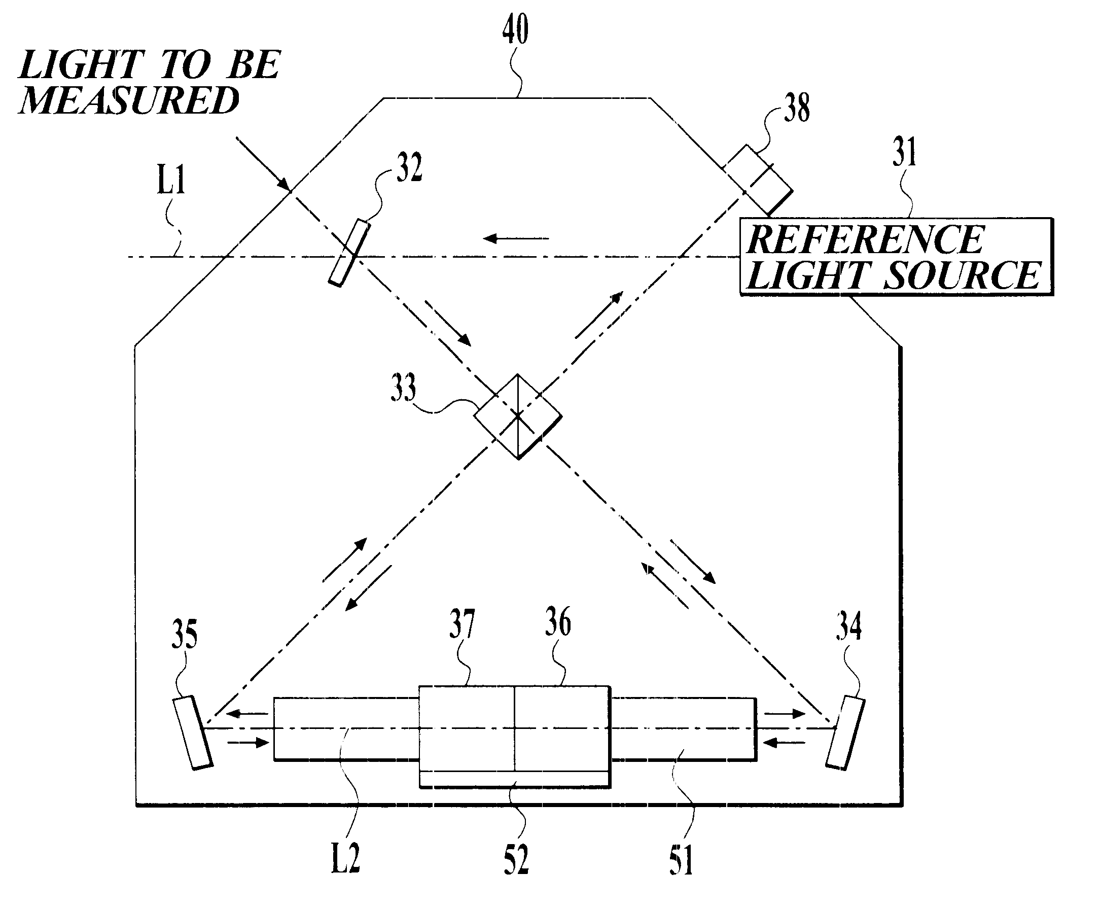
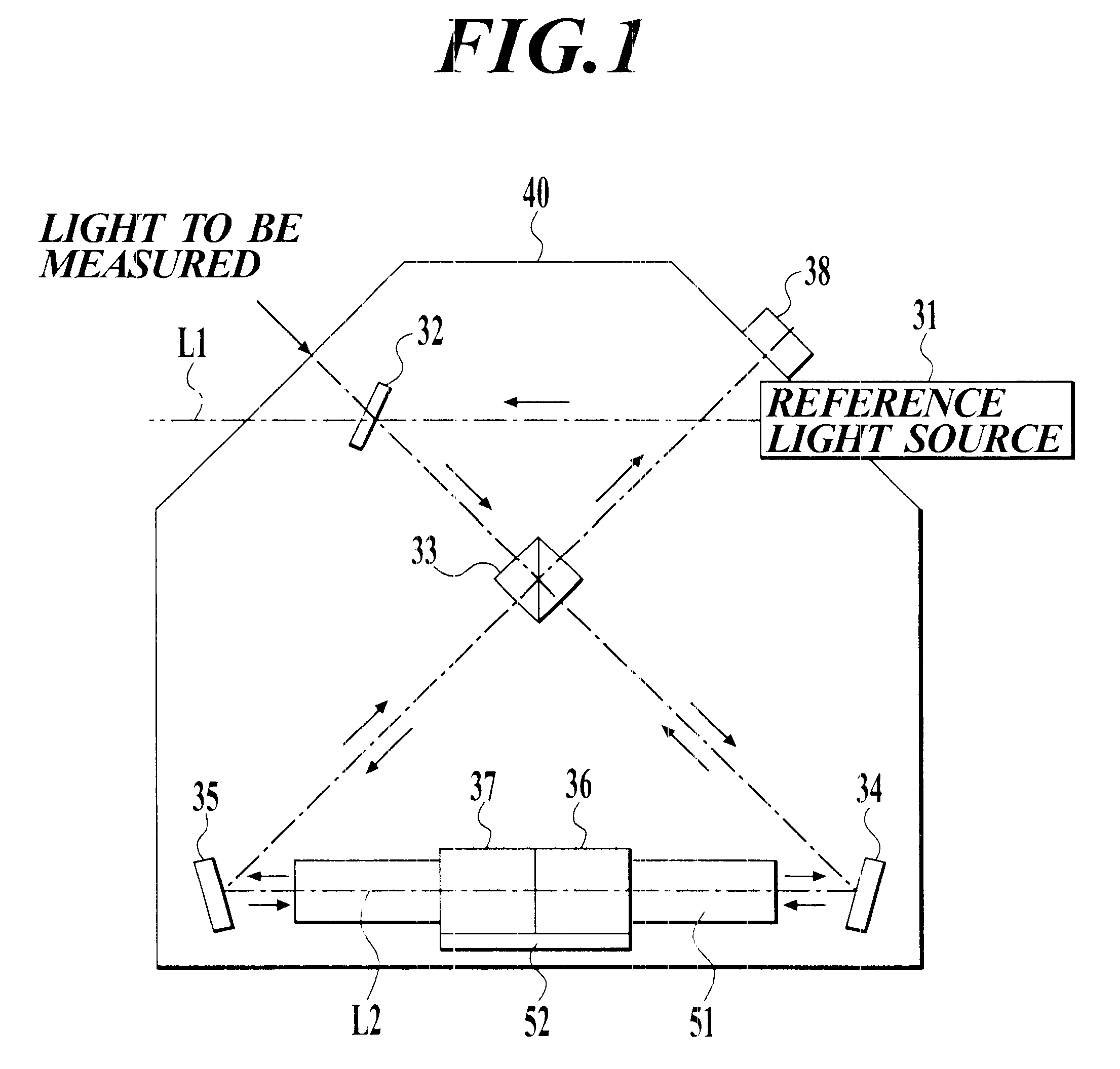
FIG. 1 is a plan view showing an example of a schematic construction of a small-sized optical interferometer as an example to which the present invention is applied. In this figure, reference numeral L1 denotes a reference optical axis, L2 denotes a movable optical axis, 31 denotes a reference light source, 32 denotes a first mirror, 33 denotes a beam splitter, 34 denotes a second mirror, 35 denotes a third mirror, 36 and 37 denote movable mirrors (corner cubes), 38 denotes a photo-detector, 40 denotes a casing, 51 denotes a linear guide, and 52 denotes a mirror base.
In the small-sized optical interferometer, an He-Ne laser is used as a reference light source 31.
As shown in FIG. 1, a reference light (an He--Ne laser light) outgoing from the reference light source 31 passes along the reference optical axis L1 and is reflected on the first mirror 32 inside the casing 40. The reference light is incident on the beam splitter 33. Further, a light to be measured, which outgoes from the ou...
second embodiment
FIG. 4 is a plan view showing an example of a schematic construction of a small-sized optical interferometer as an example to which the present invention is applied. In this figure, reference numeral L11 denotes a reference optical axis, L12 denotes a movable optical axis, 131 denotes a reference light source, 132 denotes a first mirror, 133 denotes a beam splitter, 134 denotes a second mirror, 135 denotes a third mirror, 136 and 137 denote movable mirrors (corner cubes), 138 denotes a photo-detector, 140 denotes a casing, 151 denotes a linear guide, and 152 denotes a mirror base.
In the small-sized optical interferometer, an He--Ne laser is used as a reference light source 131.
As shown in FIG. 4, a reference light (an He--Ne laser light) outgoing from the reference light source 131 passes along the reference optical axis L11 and is reflected on the first mirror 132 inside the casing 140. The reference light is incident on the beam splitter 133. Further, a light to be measured, which...
third embodiment
FIG. 8 is a plan view showing an example of a schematic construction of a small-sized optical interferometer as an example to which the present invention is applied. In this figure, reference numeral L21 denotes a reference optical axis, L22 denotes a movable optical axis, 231 denotes a reference light source, 232 denotes a first mirror, 233 denotes a beam splitter, 234 denotes a second mirror, 235 denotes a third mirror, 236 and 237 denote movable mirrors (corner cubes), 238 denotes a photo-detector, 240 denotes a casing, 251 denotes a linear guide, and 252 denotes a mirror base.
In the small-sized optical interferometer, an He--Ne laser is used as a reference light source 231.
As shown in FIG. 8, a reference light (an He--Ne laser light) outgoing from the reference light source 231 passes along the reference optical axis L21 and is reflected on the first mirror 232 inside the casing 240. The reference light is incident on the beam splitter 233. Further, a light to be measured, which...
PUM
 Abstract
Description
Claims
Application Information