Light reflection mechanism, optical interferometer and spectrometric analyzer

a technology of optical interferometer and spectrometric analyzer, which is applied in the direction of interferometric spectrometry, optical radiation measurement, instruments, etc., can solve the problems of cost reduction, energy saving, and ineffective utilization of mems technology, and achieve compact, energy-saving, and low cost. high-performance, compact

Inactive Publication Date: 2016-03-22
KONICA MINOLTA INC
View PDF19 Cites 3 Cited by
  • Summary
  • Abstract
  • Description
  • Claims
  • Application Information

AI Technical Summary

Benefits of technology

[0051]The present invention provides a light reflection mechanism, an optical interferometer, and a spectrometric analyzer which are compact, energy-saving, inexpensive, yet high-performance since the mechanism includes: a first moving portion having a reflection surface on the surface thereof; a supporting portion which supports the first moving portion; a first beam and a translating beam which couple the first moving portion and the supporting portion together in a cantilever beam structure each at the upper part and the lower part of the supporting portion; and a driving portion which moves the first moving portion, and since a large amplitude can be obtained by small energy since the first moving portion is vibrated in resonance in the direction perpendicular to the first reflection surface.
[0052]The present invention further provides a light reflection mechanism, an optical interferometer, and a spectrometric analyzer which are compact, energy-saving, inexpensive yet high-performance since the embodiment includes: first and second moving portions each having a reflection surface thereon which is formed on the same plane; supporting portions which support the first and second moving portions; a first beam which couples the first moving portion and the supporting portion together; a second beam which couples the second moving portion and the supporting portion together; and a driving portion which moves the first and second moving portions, and since the first and second moving portions are moved in opposite phases in the direction perpendicular to the reflection surface on the surfaces of the first and second moving sections, the displacement of the first and second moving portions can be reduced by half, and a step of positioning the first and second moving portions can be eliminated.

Problems solved by technology

This will result in an increase in the device size and hence production cost, with the result that the advantages of the MEMS technology cannot be effectively utilized.
When the aforementioned technologies are considered from this point of view, there are issues of downsizing, energy saving, and cost reduction with the method of the Non-Patent Document 1.

Method used


Image

  • Light reflection mechanism, optical interferometer and spectrometric analyzer
  • Light reflection mechanism, optical interferometer and spectrometric analyzer
  • Light reflection mechanism, optical interferometer and spectrometric analyzer

Examples


first embodiment

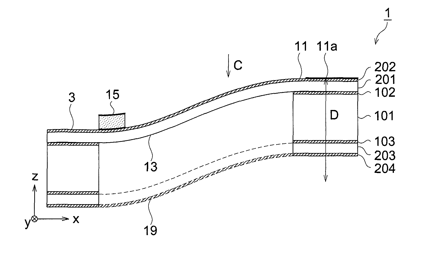
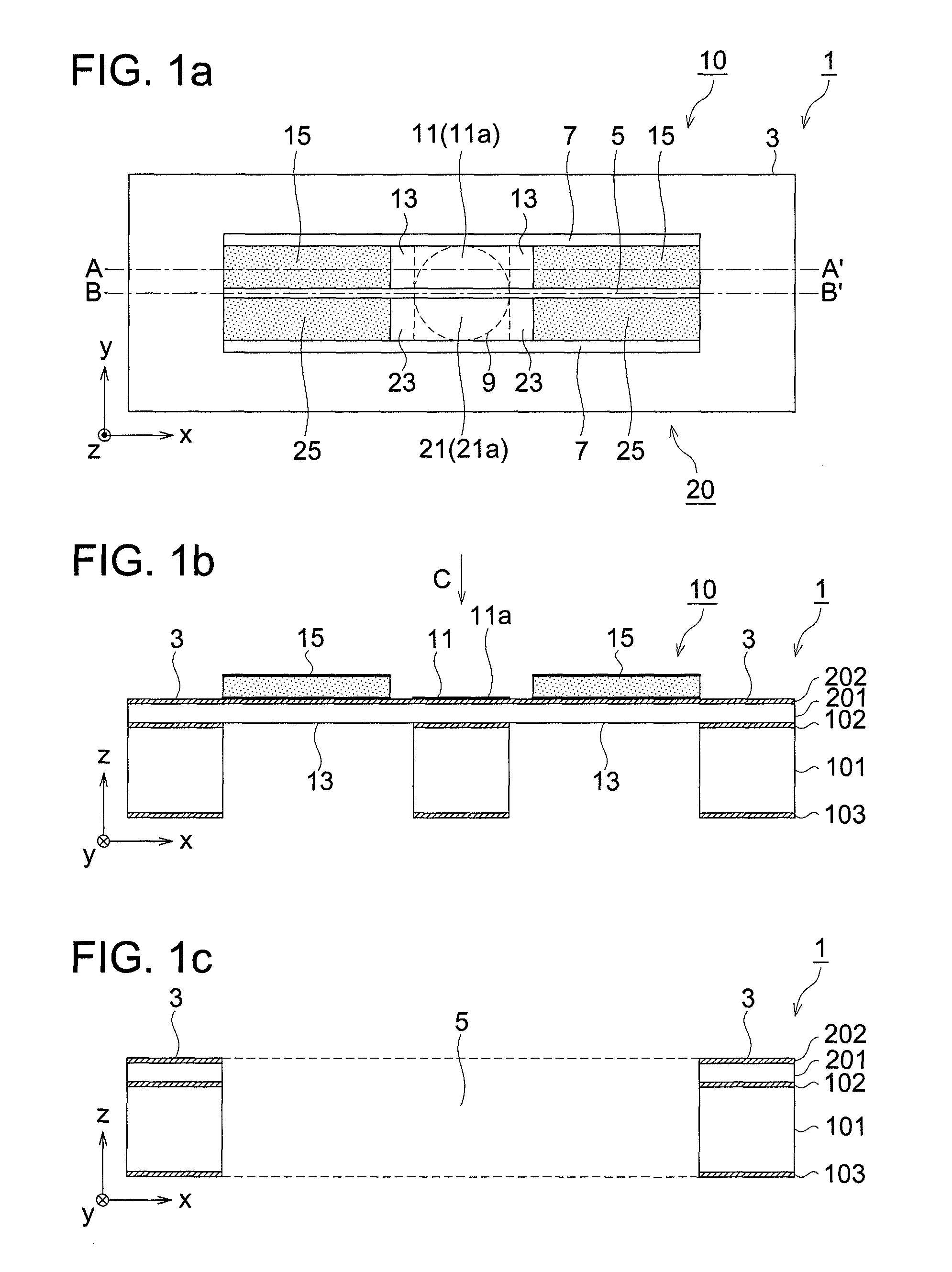
[0082]The manufacturing procedure will be described with reference to FIG. 3 and the later diagrams. In the first embodiment, the light reflection mechanism 1 is formed by processing the SOI (Silicon On Insulator) substrate by MEMS technique. The supporting portion 3, the first moving portion 11 and the second moving portion 21 are made up of a thick substrate layer 101 and thin active layer 201 of the SOI substrate. The two first beams 13 and the two second beams 23 are made up of a thin active layer 201 of the SOI substrate and others.

[0083]The supporting portion 3 is made up of a thick substrate layer 101 and thin active layer 201 of the SOI substrate to realize high rigidity of the supporting portion 3. Further, the first moving portion 11 and the second moving portion 21 are made up of the thick substrate layer 101 and the thin active layer 201 of the SOI substrate to realize high rigidity of the first moving portion 11 and the second moving portion 21 and keep the distortion o...

second embodiment

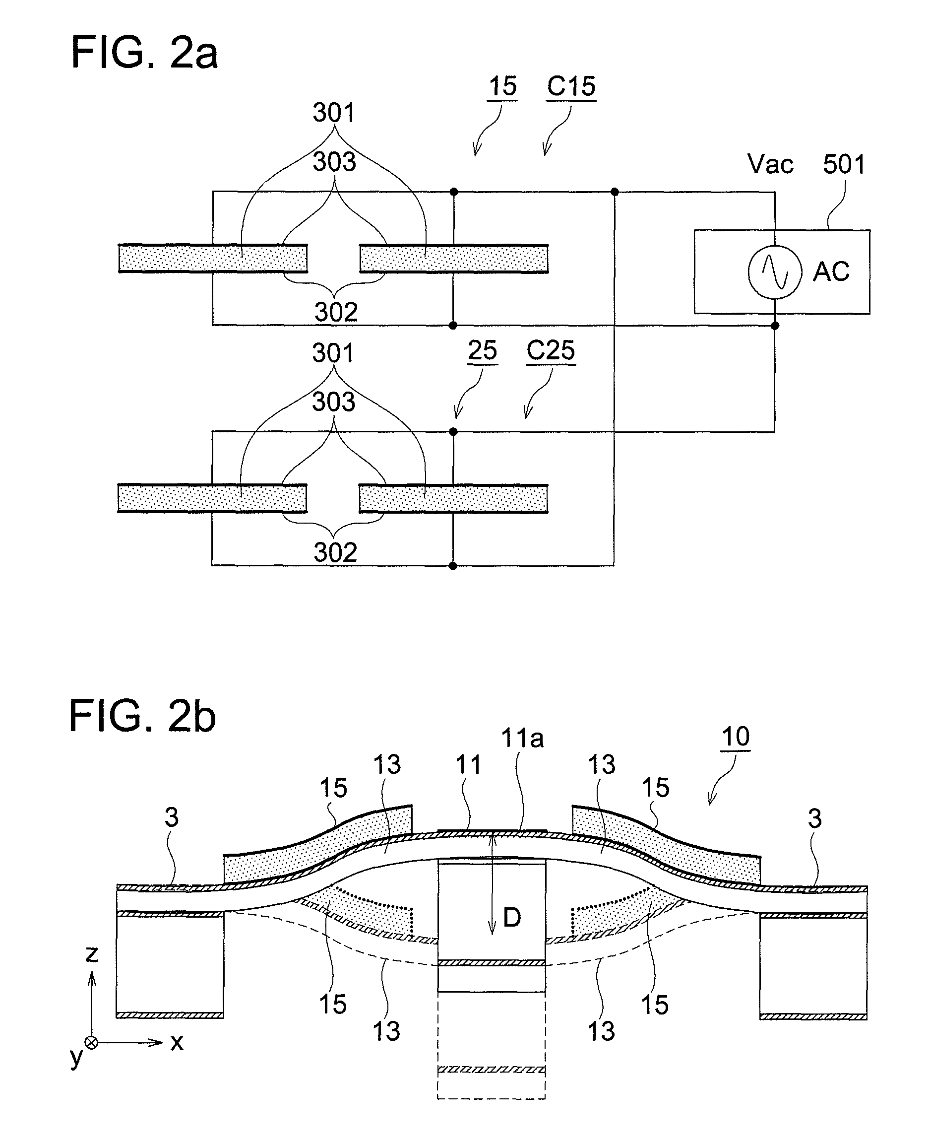
[0133]In the above-mentioned configuration, when the sine waves in opposite phases described with reference to FIGS. 2a and 2b are applied to the piezoelectric elements 15 and 25, the resonance vibration of the piezoelectric element 15 is transferred to the first beams 13 through the vibration transfer portions 8, and the first moving portion 11 accordingly vibrates in resonance in the z-axis direction. Similarly, the second moving portion 21 vibrates in resonance in the z-axis direction in the phase opposite to that of the first moving portion 11. The interference between the resonance vibration of the piezoelectric element 15 and that of the piezoelectric element 25 are separated by the gap portion 5 and then eliminated.

[0134]As described above, the second embodiment of the light reflection mechanism provides a light reflection mechanism, an optical interferometer, and a spectrometric analyzer which are compact, energy-saving, inexpensive yet high-performance and which includes: f...

third embodiment

[0140]As described above, the light reflection mechanism provides a light reflection mechanism, an optical interferometer, and a spectrometric analyzer which are compact, energy-saving, inexpensive yet high-performance since the embodiment includes: first and second moving portions each having a reflection surface thereon which is formed on the same plane; supporting portions which support the first and second moving portions; a first beam which couples the first moving portion and the supporting portion together; a second beam which couples the second moving portion and the supporting portion; a drive element provided on a portion 3a, of the supporting portion 3, along the gap portion 7 and utilizes the deformation caused by heat, and a vibration transfer portion provided between the supporting portion and the first and second beams, and since the first and second moving portions are moved in opposite phases in the direction perpendicular to the reflection surface on the surfaces o...


PUM


Abstract

Provided is an inexpensive, high performance, compact, and energy saving light reflection mechanism comprising a first moving portion having a reflecting surface on the front surface, a supporting portion which supports the first moving portion, a first beam and a translating beam which couple the first moving portion and the supporting portion in the form of cantilever beam above and below the supporting portion, and a drive portion which moves the first moving portion, wherein a large amplitude can be obtained by small energy when the first moving portion is forced into resonance vibration in the direction perpendicular to the first reflecting surface. Also provided is an optical interferometer and a spectral analyzer.

Description

RELATED APPLICATIONS[0001]This application is a U.S. National Phase Application under 35 USC 371 of International Application PCT / JP2010 / 055677 filed Mar. 30, 2010.[0002]This application claims the priority of Japanese application No. 2009-105071 filed Apr. 23, 2009, the entire content of which is hereby incorporated by reference.TECHNICAL HELD[0003]The present invention relates to a light reflection mechanism, optical interferometer and spectrometric analyzer, particularly to a light reflection mechanism, optical interferometer and spectrometric analyzer formed by the microfabrication technology.BACKGROUND ART[0004]Optical interferometers have been used in the field of examining the profile of an optical element such as a lens or a prism. Namely, the light from a laser source is separated into two beams, and one of these beams is passed through a test piece (hereinafter referred to as “sample”) such as a lens or a prism. After that, these two beams having been separated are put tog...

Claims


Application Information

Patent Timeline
Patent Type & Authority Patents(United States)
IPC IPC(8): G01J3/45G01J3/453G01B9/02G01J3/02G02B26/00G01M11/02G01J9/02
CPCG01B9/02044G01B9/02057G01B9/02097G01J3/02G01J3/021G01B9/02024G01J3/4535G01J9/02G01M11/025G01M11/0271G02B26/001G01B2290/35
Inventor MATSUDA, SHINYAHIROSE, SATORU
Owner KONICA MINOLTA INC
Why Eureka
Try Eureka