Optical multi-species gas monitoring sensor and system

a multi-species, gas monitoring technology, applied in the direction of instruments, gas/flame sensing radiation, interferometric spectrometry, etc., can solve the problems of low detection accuracy, low detection efficiency, and low accuracy of gas monitoring sensors and systems

Active Publication Date: 2012-12-11
NASA
View PDF14 Cites 3 Cited by
  • Summary
  • Abstract
  • Description
  • Claims
  • Application Information

AI Technical Summary

Problems solved by technology

In general, there are several methods to detect the presence of a gas in vacuum, but no off-the-shelf instrument is particularly well-suited for multiple gas species leak detection that can occur on various times scales and lead to pressure levels in the vicinity of the leak that span several orders of magnitude.
High-vacuum gauges (ion gauges) are quite accurate at low pressures, but they are relatively fragile and their filaments can become damaged if operation is attempted above 1 milliTorr for any prolonged period of time.
Furthermore, high-vacuum gauges generate heat that could ignite a leaking combustible propellant.
Mass spectrometers can be large and are difficult to locate in space-limited or remote locations.
In addition, their operation requires high-voltage, the presence of which is generally not desirable next to a liquid hydrogen or oxygen tank.
Reactive coupons (e.g., palladium-catalyzed silicon carbide) are generally species specific and can severely outgas in a vacuum environment to the point of uselessness.

Method used


Image

  • Optical multi-species gas monitoring sensor and system
  • Optical multi-species gas monitoring sensor and system

Examples


Embodiment Construction

)

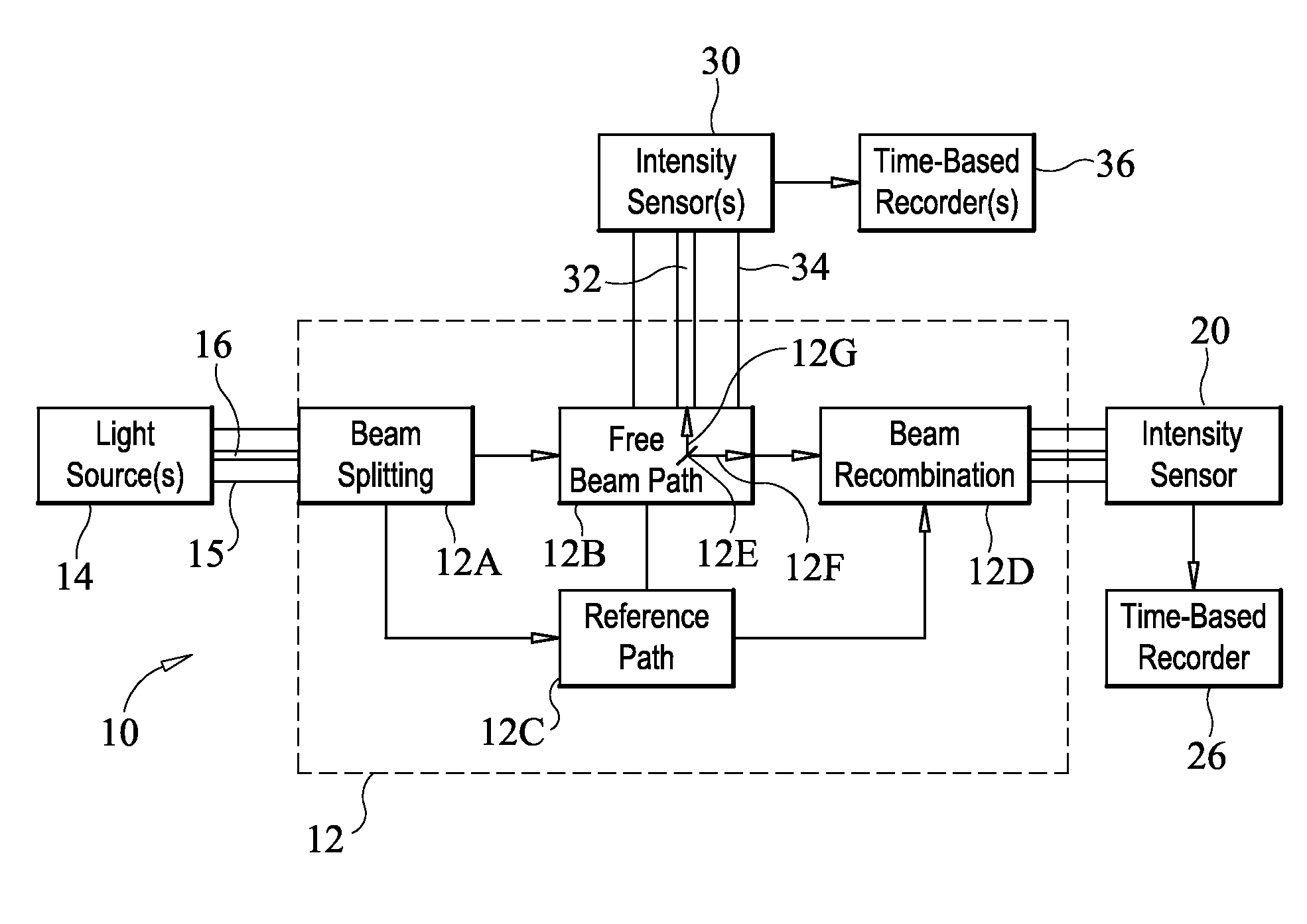
[0015]Referring now to the drawings and more particularly to FIG. 1, a block diagram of a gas monitoring sensor and system in accordance with an embodiment of the present invention is shown and is referenced generally by numeral 10. By way of illustrative example, the present invention will be described for its use in monitoring the leakage of multiple species of gas into a non-gaseous vacuum environment. Monitoring will generally take place outside of a positive-pressure container that stores a gas (or liquid). For example, the container could be cryogenic liquid storage tank parked in a spatial orbit or deployed on a lunar or other planetary surface. In either of these situations, it is assumed that the environment surrounding the storage tank is a non-gaseous space environment.

[0016]At the heart of system 10 is a multi-species gas sensor 12 positioned where gas monitoring is of interest. Sensor 12 incorporates an optical interferometer that can be constructed in accordance with ...


PUM


Abstract

The system includes at least one light source generating light energy having a corresponding wavelength. The system's sensor is based on an optical interferometer that receives light energy from each light source. The interferometer includes a free-space optical path disposed in an environment of interest. The system's sensor includes an optical device disposed in the optical path that causes light energy of a first selected wavelength to continue traversing the optical path whereas light energy of at least one second selected wavelength is directed away from the optical path. The interferometer generates an interference between the light energy of the first selected wavelength so-traversing the optical path with the light energy at the corresponding wavelength incident on the optical interferometer. A first optical detector detects the interference. At least one second detector detects the light energy at the at least one second selected wavelength directed away from the optical path.

Description

ORIGIN OF THE INVENTION[0001]The invention described herein was made in the performance of work under a NASA contract and by an employee of the United States Government and is subject to the provisions of Public Law 96-517 (35 U.S.C §202) and may be manufactured and used by or for the Government for governmental purposes without the payment of any royalties thereon or therefore. In accordance with 35 U.S.C §202, the contractor elected not to retain title.CROSS-REFERENCE TO RELATED PATENT APPLICATIONS[0002]This patent application is co-pending with one related patent application entitled “OPTICAL SYSTEM AND METHOD FOR GAS DETECTION AND MONITORING”, Ser. No. 12 / 336,260, filed Dec. 16, 2008, and owned by the same assignee as this patent application.BACKGROUND OF THE INVENTION[0003]1. Field of the Invention[0004]This invention relates to gas detection and monitoring. More specifically, the invention is an optical-based sensor and system for monitoring a variety of gases particularly in ...

Claims


Application Information

Patent Timeline
Patent Type & Authority Patents(United States)
IPC IPC(8): G01B9/02
CPCG01J1/12G01J3/45G01N21/31G01N21/45G01J5/0014G01N2021/3185G01N2021/451
Inventor POLZIN, KURT A.KORMAN, VALENTIN
Owner NASA
Why Eureka
Try Eureka