Electrical contact interface

a technology of contact interface and electrical contact spring, which is applied in the direction of coupling contact members, coupling device connections, electrical apparatus, etc., can solve the problems of common exposure to extreme heat, pressure, g-forces and vibrations, and achieve the effect of economic construction

Inactive Publication Date: 2003-01-14
SMITHS INTERCONNECT AMERICAS INC
View PDF2 Cites 88 Cited by
  • Summary
  • Abstract
  • Description
  • Claims
  • Application Information

AI Technical Summary

Benefits of technology

e) to provide such a spring probe and interface device which is particularly well adapted for the intended purpose and is economical of construction.

Problems solved by technology

These units are commonly subjected to extreme heat, pressure, g-forces and vibrations and must maintain electrical contacts between components for functionality.

Method used


Image

  • Electrical contact interface
  • Electrical contact interface

Examples


Embodiment Construction

As required, detailed descriptions of the preferred and alternate embodiments are disclosed herein, however, it is to be understood that the disclosed embodiments are merely exemplary of the invention which may be embodied in various forms. Therefore, specific structural and functional details herein are not to be interpreted as limiting, but merely as a basis for the claims and as a representative basis for teaching one skilled in the art to variously employ the present invention in virtually any appropriately detailed structure.

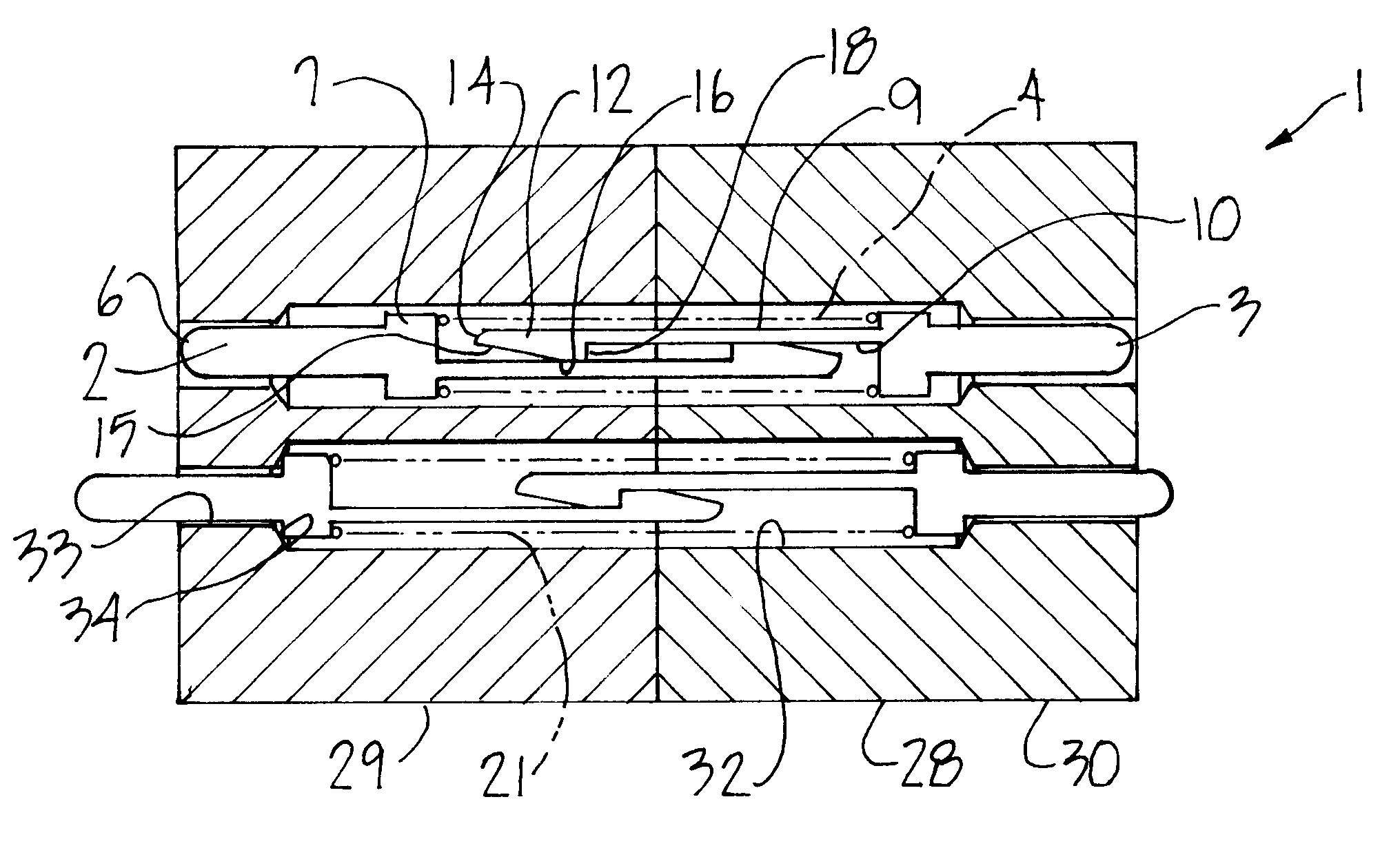
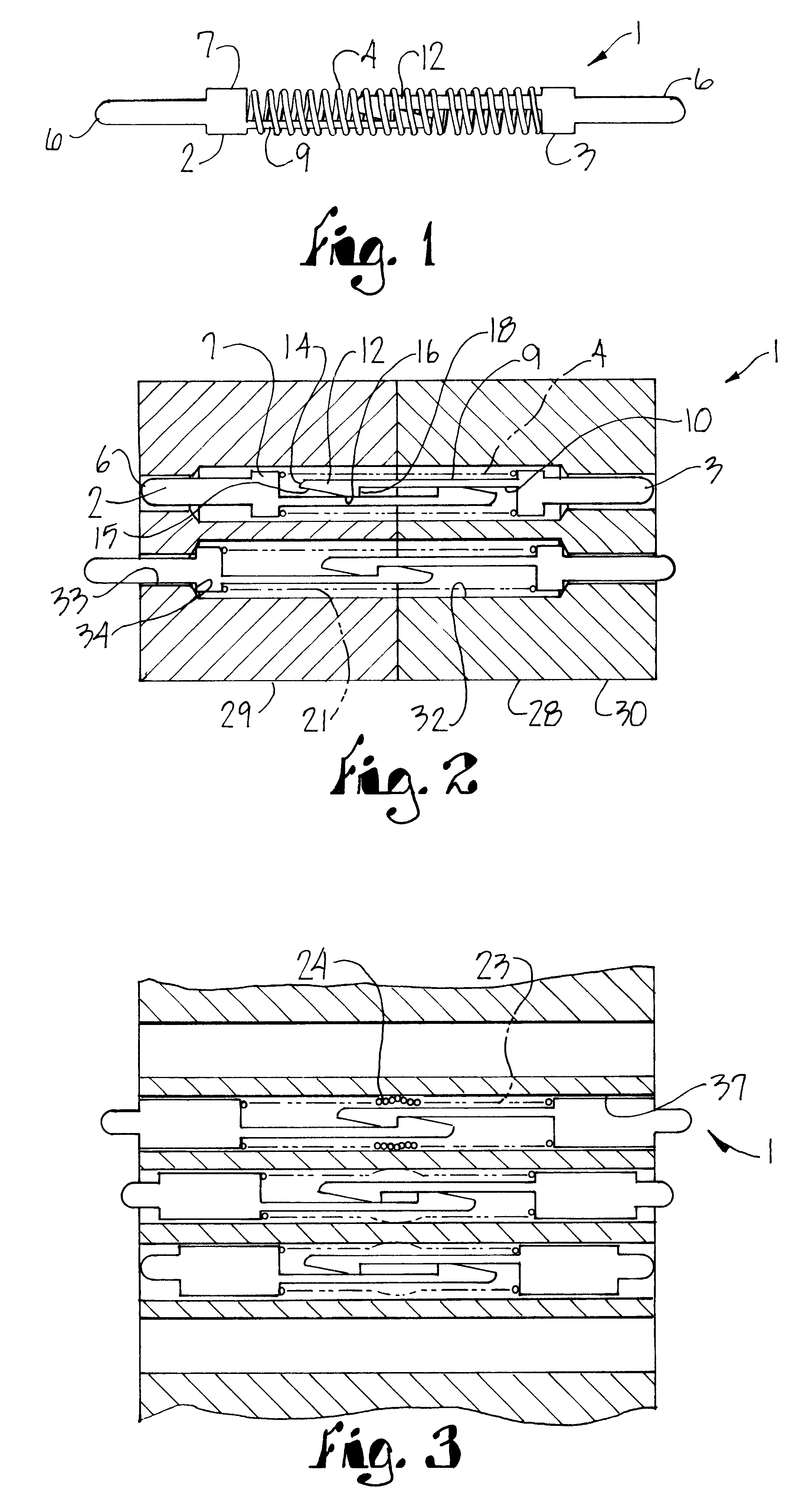
The reference numeral 1, FIG. 1 generally indicates a spring contact interconnect probe embodying the present invention. The probe 1 generally consists of a pair of oppositely extending plungers 2 and 3 which are connected together as hereinafter described and biased to an outwardly extended relative position by a biasing means 4. In further detail, each of the plungers 2 and 3 has an outer end terminating in a contact tip 6 which engages an electrical site...


PUM


Abstract

An electrical contact interface consists of a probe formed by a pair of oppositely extending plungers each having a contact tip, an inner shoulder and a rearwardly extending shaft terminating in a lug end. A coil spring is sleeved about the opposed plungers and is positioned between the opposite inner shoulders with the shafts extending toward each other and in constant sliding engagement with each other through the lug ends. The lug ends abut each other at an extreme travel relation of the plungers and prevent mutual disengagement of the plungers from within the coil spring. The probe is mounted in a fixture or other intermediate structure for positioning between circuit contacts. The probe finds particular use in applications requiring robust design and in which electrical contact must be maintained.

Description

This invention relates to spring contact probes in general and particularly to such probes that are used in fixture interfaces for use in applications requiring particularly robust design.Spring probes for electrical interfaces are well known in the prior art and represent a wide family of technology for providing interconnection between electrical contact points. Some spring probes are designed for circuit testing and are suited for placing in a matrix providing an interface between a testing circuit computer and a device under test, which is ordinarily an integrated chip or a circuit board. While some circuit boards are loaded with components and then tested when completed, a preferred method of manufacture is to test circuit boards and if passed, then stuff the board with the necessary components to create the full circuit, as this procedure is much more cost effective if the circuit board is defective. Other spring probes are used in interfaces when components may be removed and...

Claims


Application Information

Patent Timeline
Patent Type & Authority Patents(United States)
IPC IPC(8): H01R13/24H01R13/22
CPCH01R13/2421
Inventor MEEK, RONTHURSTON, WILLIAM E.
Owner SMITHS INTERCONNECT AMERICAS INC
Why Eureka
Try Eureka