
Game decoy with high-speed, rotating "strobe" wings and in-line motor drive

a high-speed, in-line motor technology, applied in the field of duck decoy system, to achieve the effect of enhancing the visibility of the decoy

Inactive Publication Date: 2003-01-21
HUNTWISE
View PDF30 Cites 44 Cited by
  • Summary
  • Abstract
  • Description
  • Claims
  • Application Information

AI Technical Summary

Benefits of technology

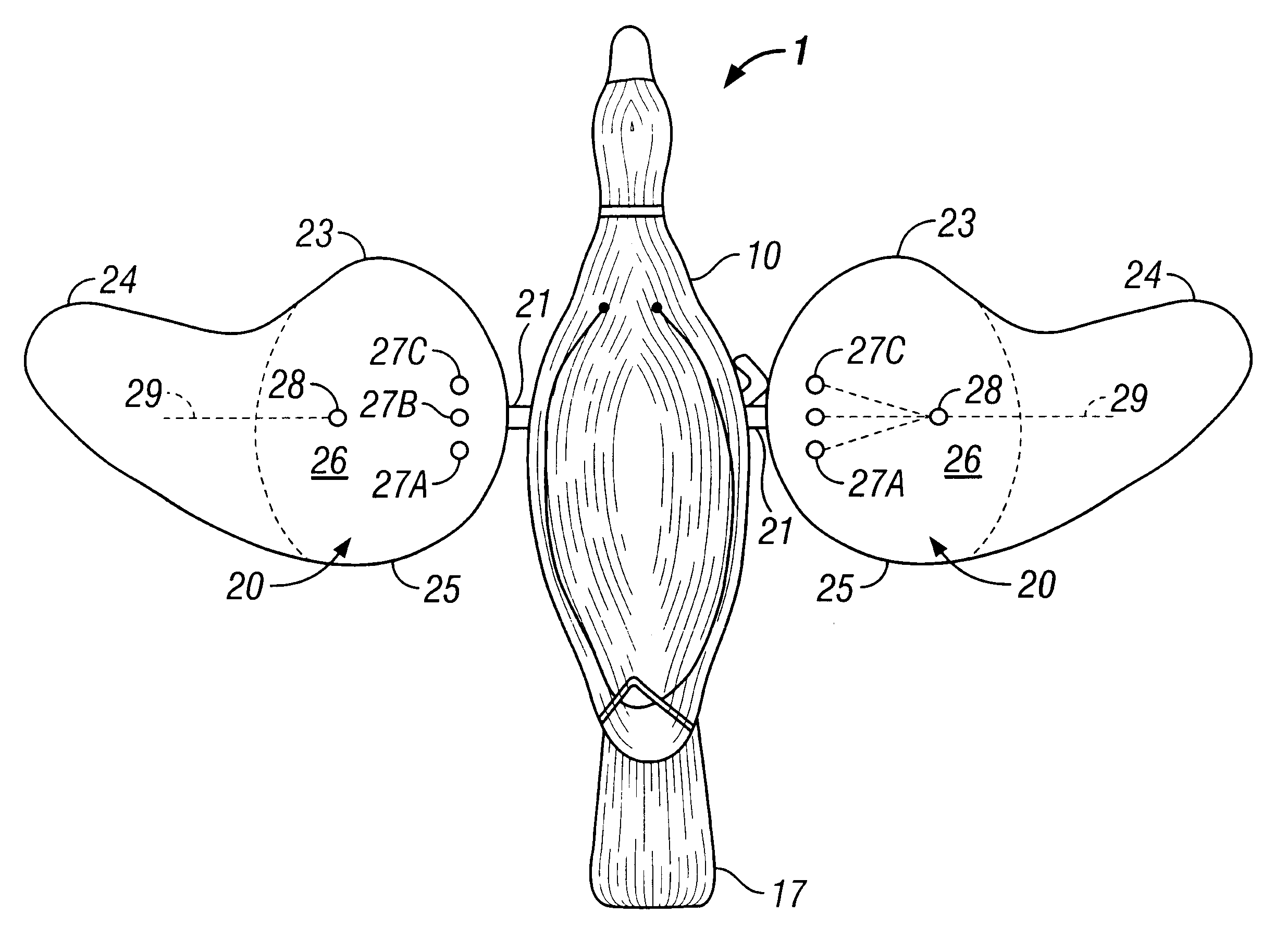
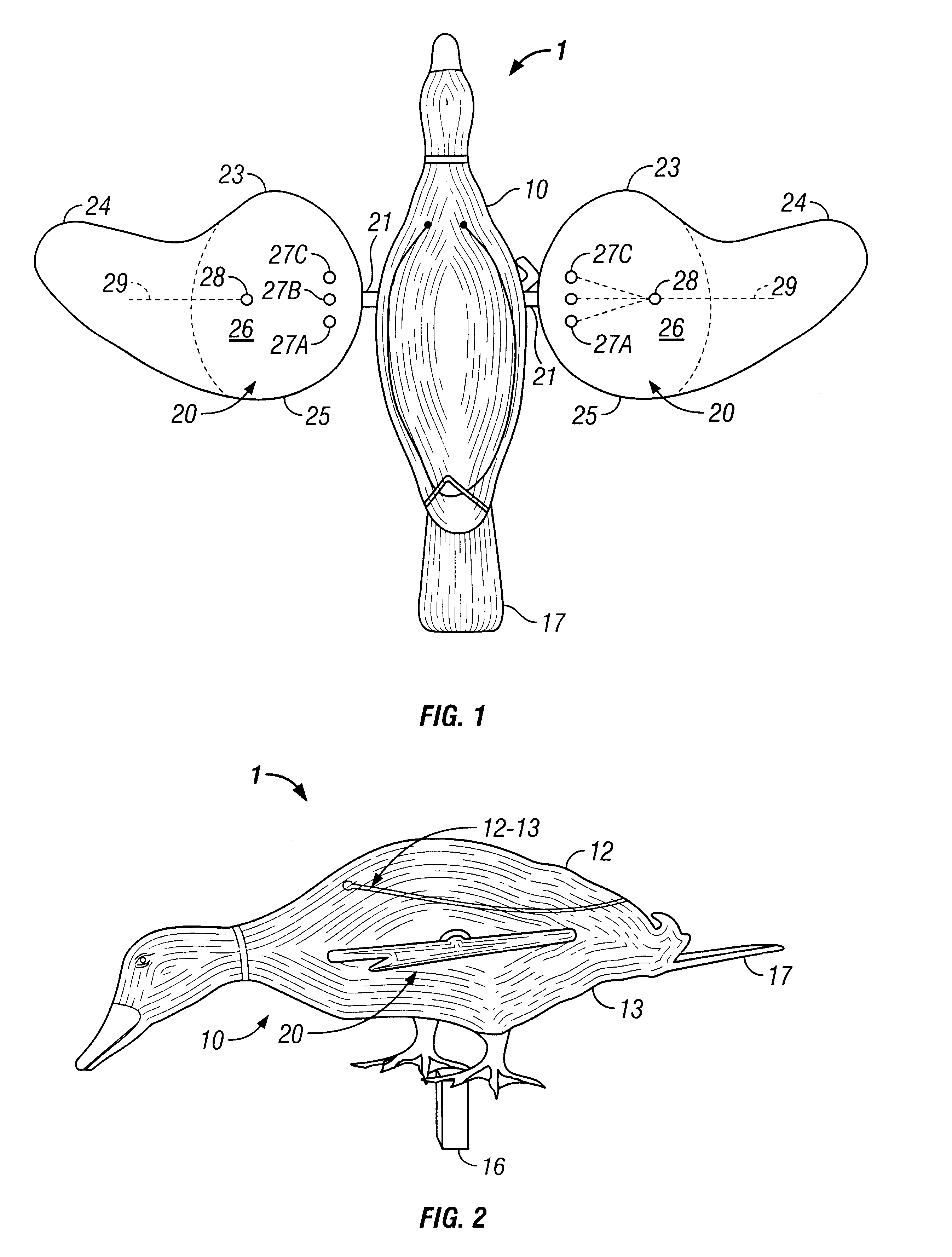
As noted above, the present invention relates to a water fowl (e.g. duck) decoy system in which the decoy's wings are preferably flat and both longitudinally and laterally extended by, for example, having one or more leading and / or trailing edge, curved lobes, producing a laterally elongated circular area, similar to the shape of a disc, preferably of a size of at least about nine (9") inches in "diameter," with contrasting colors (e.g., drab olive or dark green & white) on its opposite, flat sides. The wings are rotated at a relatively high speed, e.g., at least about six hundred (.about.600 rpm+) revolutions per minute or more, producing in conjunction with the size, configuration and contrasting colors of the wings, a "strobe" like effect for enhanced visibility of the decoy to flying water fowl (e.g. ducks).
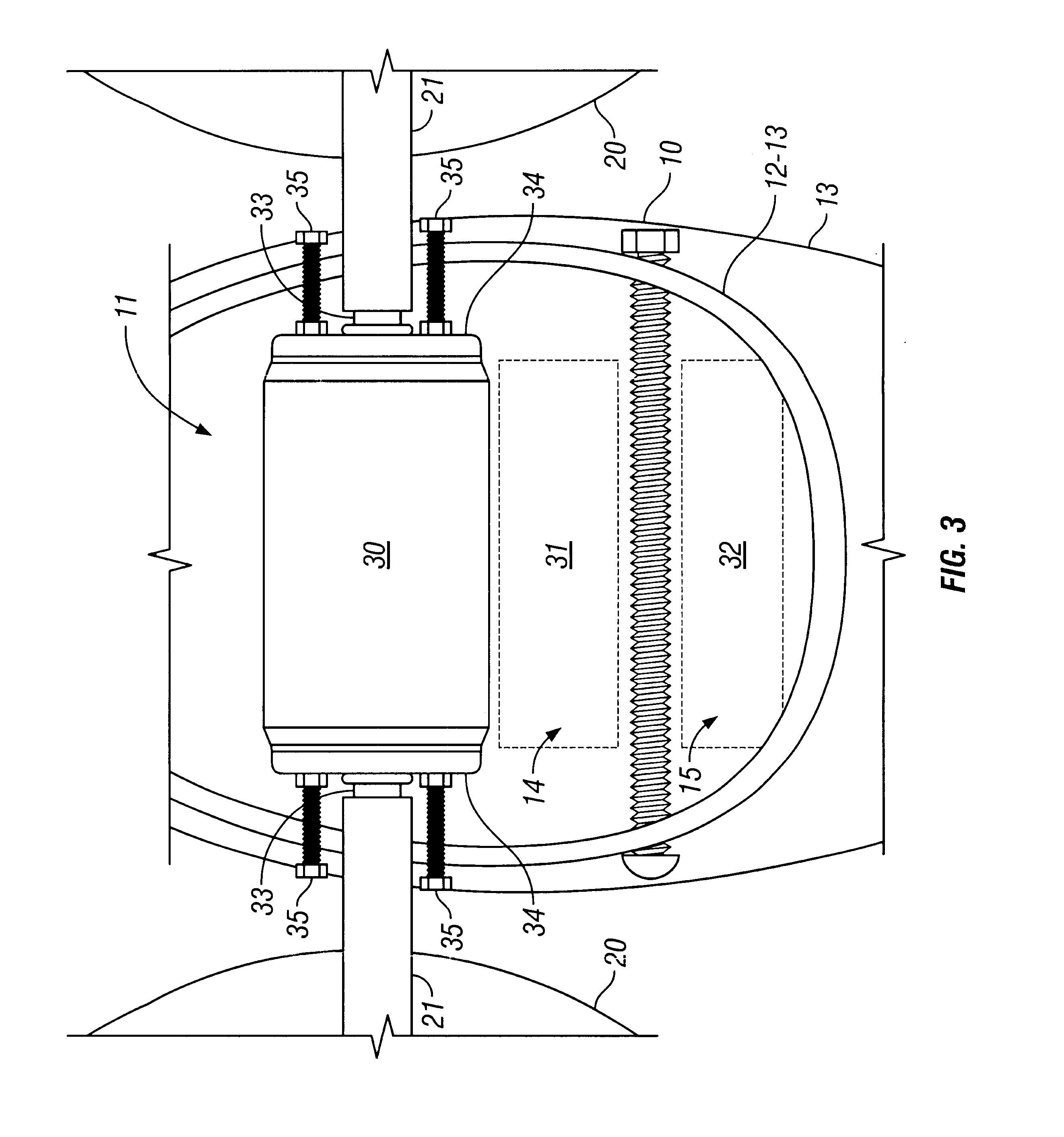
Additionally, the decoy has a laterally disposed, direct, in-line electric motor drive, with laterally directed, dual shaft connectors going directly to the wings for a simple, direct, in-line interconnection or direct drive. The center-lines of the wings effectively may be connected to the motor shaft at varying angles, producing a variable, wing "flapping" like effect as the wings are rotated.

Problems solved by technology

The problem with these floating, but otherwise static, decoys is that they show no evidence of individual movement, and live ducks soon become "decoy wise".

Method used


Image

  • Game decoy with high-speed, rotating "strobe" wings and in-line motor drive
  • Game decoy with high-speed, rotating "strobe" wings and in-line motor drive
  • Game decoy with high-speed, rotating "strobe" wings and in-line motor drive

Examples


Embodiment Construction

As can be seen in FIGS. 1-3, the first, currently preferred, exemplary embodiment of the water fowl decoy system of the present invention is based on, for example, a duck decoy 1 including a body 10 emulating the body of an actual duck (e.g., a mallard), two, substantively identical, rotatable wings 20 (shown with their "trailing" edges in the forward position), and a laterally disposed, in-line, DC motor 30 (note FIGS. 3 & 3A), directly connected or coupled to the wing shafts 21 by means of, for example, set screws 22 (note FIG. 3A).

The DC motor 30 preferably is a relatively substantial, heavier duty, double shaft, direct drive motor capable of handling a range of voltages from about, for example, twelve or less (e.g. down to about 6 v but preferably 12+volts) up to about, for example, ninety (12-90v) volts, preferably powered by a pair of lantern type, DC batteries 31 & 32 in series delivering at least twelve (12 v) volts. The motor 30 is included as a double shaft, direct drive m...


PUM


Abstract

A water fowl (e.g. duck) decoy system in which the decoy's wings (20 / 120), which are flat and both longitudinally and laterally extended by, for example, having one or more, curved lobes (23 / 123A&B, note FIGS. 1& 5B), producing a disc like shape, preferably of a size of at least about nine (9'') inches in "diameter," with contrasting colors (e.g., dark olive & white; cf. FIGS. 5B & 5C) on its flat sides with one or more stripes on its lighter side, are rotated at a relatively high speed (e.g., ~600 rpm+, e.g., more particularly ~600 or ~750 rpm or up to ~900 rpm or greater), producing a "strobe" like effect for enhanced visibility of the decoy to flying ducks. Additionally, the decoy (1 / 101) has a laterally disposed, direct, in-line, DC electric motor drive (30), with laterally directed, dual shaft connectors (note FIG. 3) directly connected to the wings. The wings may be connected to the dual motor shafts with their respective center-lines (29) either co-incidental or at varying angles (note set of proximal connector holes 27A-C of FIG. 3), producing a variable, wing "flapping" like effect when angled, i.e., not-co-incident.

Description

The present invention relates to a water fowl decoy system, using a decoy body emulating, for example, a mallard duck, in which the decoy's wings, which are flat and both longitudinally and laterally extended with contrasting color on its flat sides, are rotated at a relatively high speed (e.g. at least about 600 rpm) producing a "strobe" like effect for enhanced visibility of the decoy to flying water fowl (e.g. ducks). Additionally, the decoy has a direct, in-line, laterally disposed, electric motor drive, with laterally directed, dual shaft connectors for rotating the wings, and the wings may be connected to the motor shaft at varying angles producing a variable, wing "flapping" like effect.The number of ducks and the interest in duck hunting are at an all time high. The acknowledged "weak link" in duck hunting is the decoys. Traditional decoys are simple plastic, duck shaped bodies used to attract live ducks. The problem with these floating, but otherwise static, decoys is that ...

Claims


Application Information

Patent Timeline
Patent Type & Authority Patents(United States)
IPC IPC(8): A01M31/00A01M31/06
CPCA01M31/06
Inventor CROWE, CLAUDE M.
Owner HUNTWISE
Learn More