Instrument cluster reflector

a technology of instrument clusters and reflectors, applied in the field of backlighting an indicating instrument, can solve the problems of reducing packaging efficiency, high part count, shortening the life of instrument clusters,

Inactive Publication Date: 2003-01-21
YAZAKI NORTH AMERICA
View PDF14 Cites 21 Cited by
  • Summary
  • Abstract
  • Description
  • Claims
  • Application Information

AI Technical Summary

Problems solved by technology

This requires a high part count and a large space requirement that reduces packaging efficiency.
The use of bulbs shortens the lif...

Method used


Image

  • Instrument cluster reflector
  • Instrument cluster reflector
  • Instrument cluster reflector

Examples


Embodiment Construction

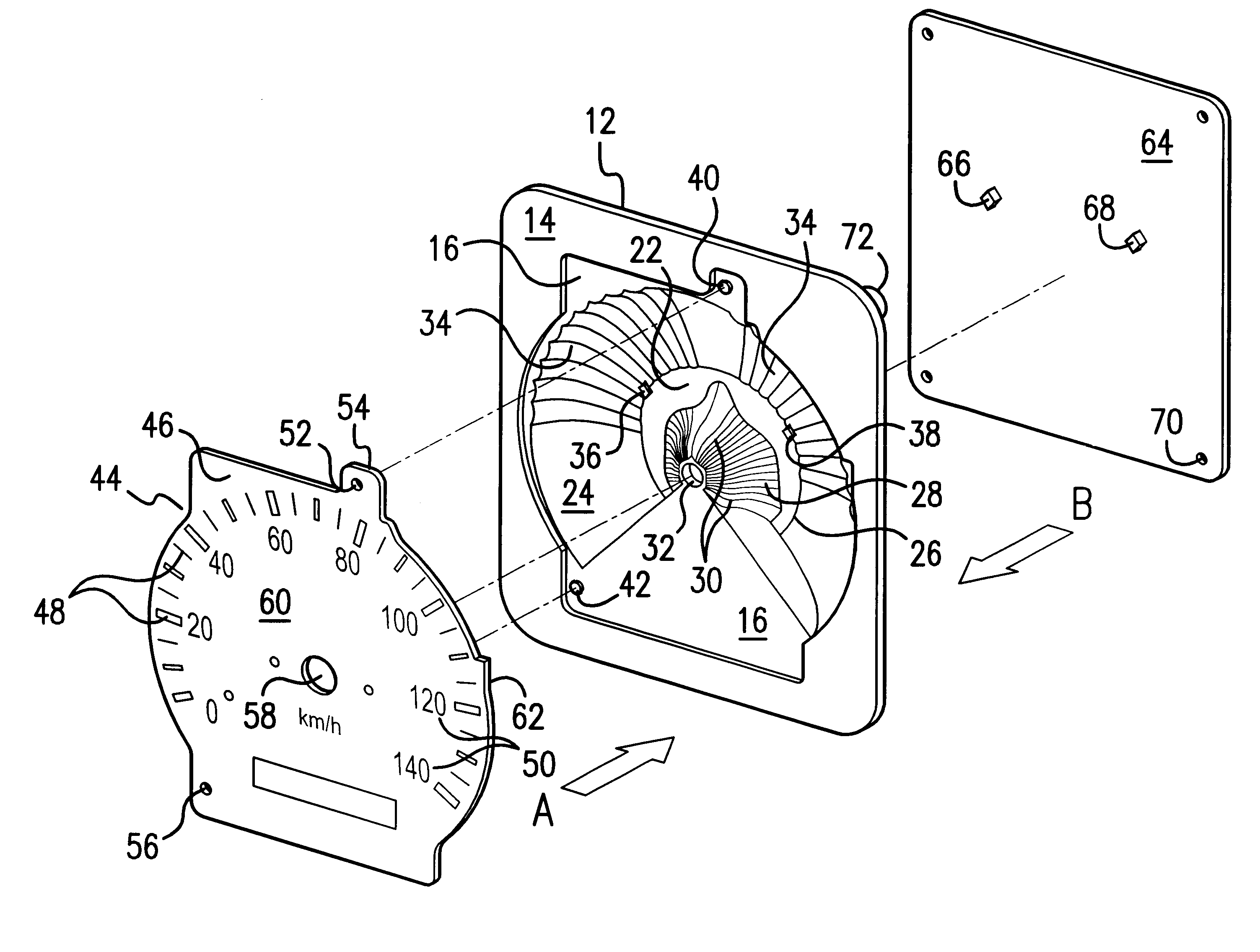
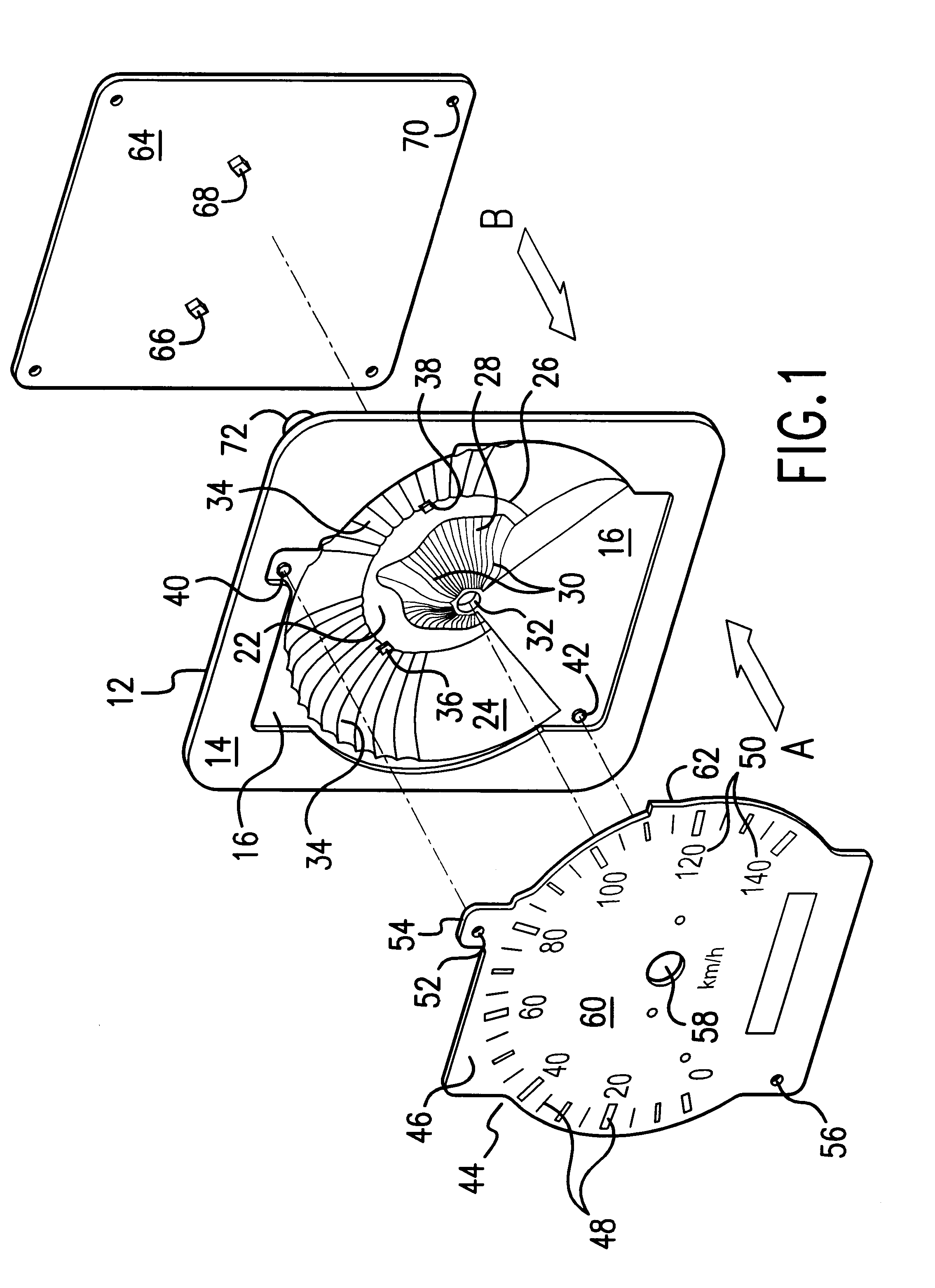
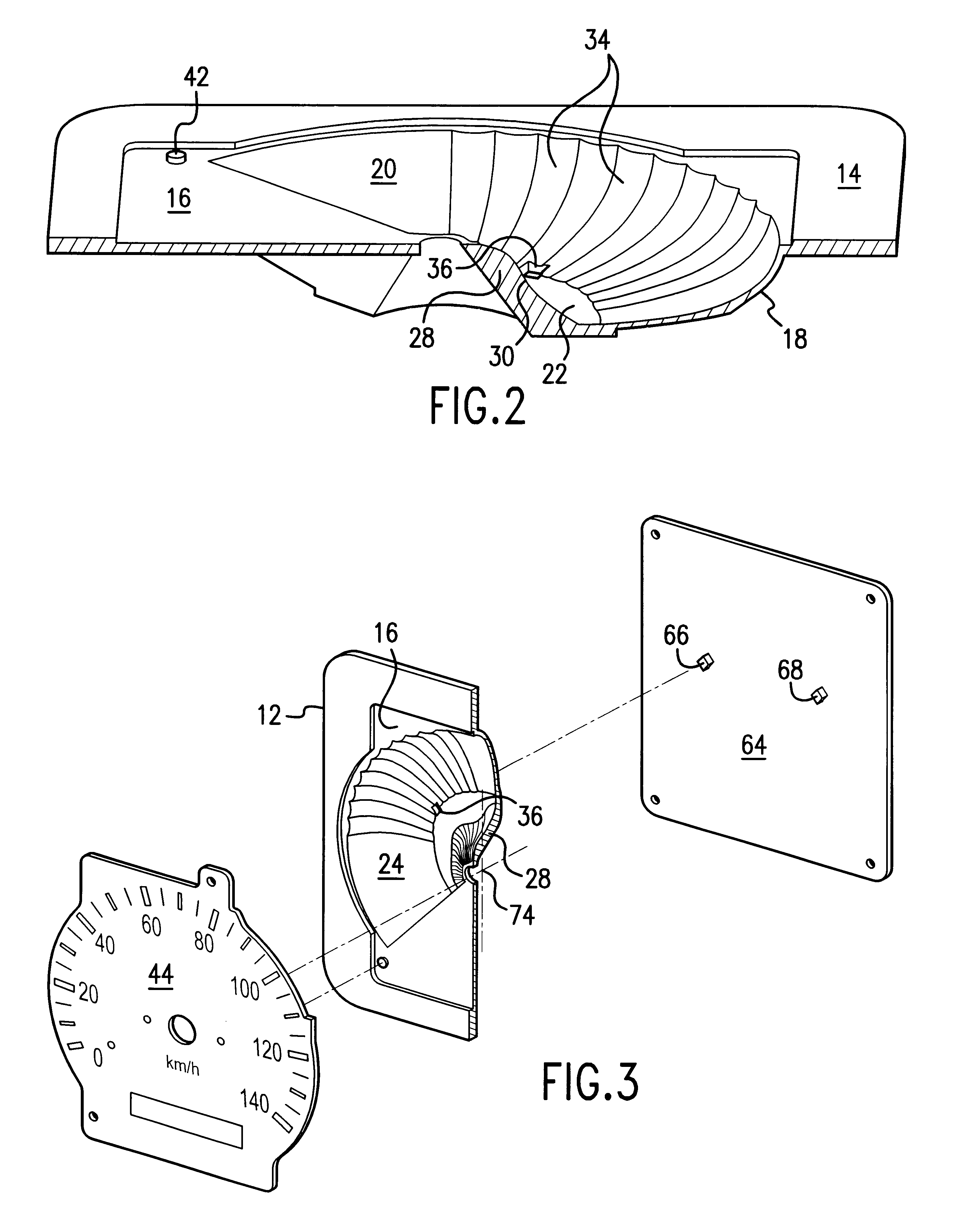
Referring now to FIGS. 1-3, a reflector 12 according to the present invention comprises a plate 14 with a recessed portion 16. A partially bowl-shaped part 18 extending away from the plate 14 is integrally joined to the recessed portion 16 and forms a compartment 20 opening in the direction of the recessed portion and plate 14. The compartment 20 has a base 22 and an semi-annular or semi-circular wall 24 extending around an outer periphery 26 of the base 22 and joining the base to the recessed portion 16 of the plate at an edge of the wall distal from the base. The base 22 has a centrally located projection 28 extending in the direction of the plate 14.

The projection 28 has an outer surface formed by or shaped as multiple parabolic flutes 30. An opening 32 extends through the projection. The semi-circular wall 24 has an inner surface facing the projection 28. The inner surface is formed by concave radial flutes 34 extending at an outward angle from the outer periphery 26 of the base...


PUM


Abstract

A reflector for backlighting an indicating instrument has two groups of flutes arranged for evenly distributing light and reducing bright spots. A plate has a recessed portion for receiving the indicating instrument and a semi-bowl-shaped compartment extending away from the plate and opening to the indicating instrument. The compartment has a base with a central projection formed by parabolic flutes and a semi-circular wall connecting the base with the recessed portion of the plate. The semi-circular wall has an inner surface facing the parabolic flutes. The inner surface has flutes extending in a radial direction from the base. Two apertures are positioned in the compartment across a boundary between the base and semi-circular wall. The apertures each receive a light emitting diode mounted on a printed circuit board when the board is assembled on the reflector. The parabolic flutes distribute the light from the light emitting diodes to evenly backlight the indicating instrument. The radial flutes diffuse the light to prevent hot or bright spots from developing under the indicating instrument. The light is further scattered by a chrome coating applied on a surface of the indicating instrument facing the compartment.

Description

1. Field of the InventionThis invention is directed in general toward a device for backlighting an indicating instrument and more specifically to a reflector that evenly and efficiently distributes light to modules in a vehicle instrument cluster.2. Discussion of Related ArtTraditionally, analog instrument clusters on vehicle instrument panels have been illuminated by an arrangement of light guides, reflectors and light bulbs. For example, U.S. Pat. No. 5,556,187 illustrates a speedometer dial lit by multiple bulbs. One reflector guides the light from the bulbs to a pointer mounted on the dial. Another reflector concentrates light from the bulbs onto the first reflector. This requires a high part count and a large space requirement that reduces packaging efficiency. The use of bulbs shortens the life of instrument clusters. In those clusters that use light guides to transmit the light from bulbs to a dial face, the dial face is often unevenly lit with some sections being brighter or...

Claims


Application Information

Patent Timeline
IPC IPC(8): B60Q3/00B60Q3/04G01D11/28
CPCG01D11/28B60Q3/044B60Q3/14B60K2370/336
Inventor VENKATRAM, SANJIVFONG, CHING
Owner YAZAKI NORTH AMERICA
Why Eureka
Try Eureka